Adder ii components, Base unit, Input/output modules – Grass Valley Adder II User Manual
Page 7: Base unit input/output modules
3
Adder II
User Guide
Adder II Components
Base Unit
Each end of an Adder system consists of at least two parts: One base frame with control unit
and one or more input/output (I/O) modules.
Fig. 1-1:
Adder II
Base Control Unit Front Panel
Base units are common to all Adder II’s no matter how large or small. This is the optical I/O
and the first building block of all systems. The base frame also has the on/off switch for the
system, the local gain controller, the data I/O’s, and to thetone generator/analyzer.
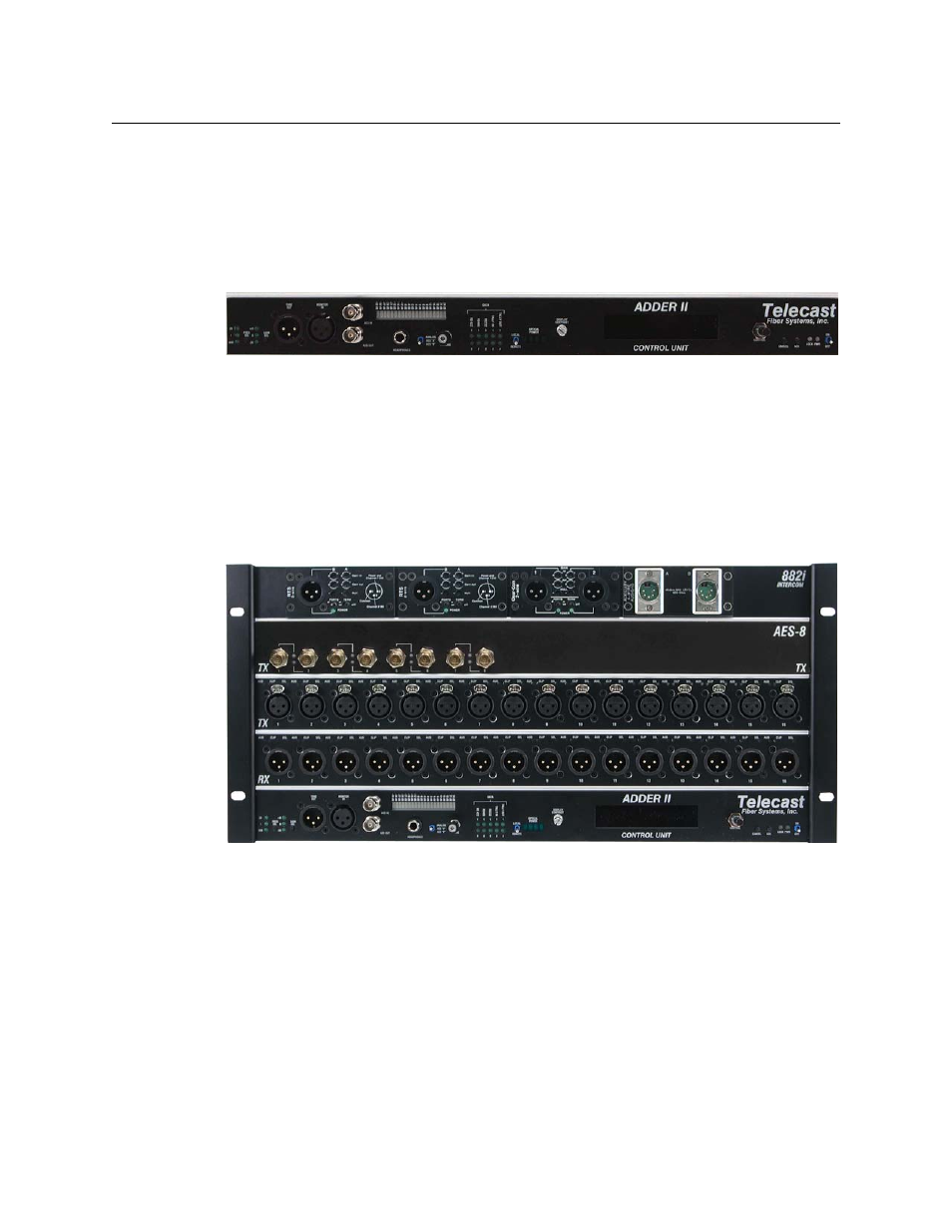
Input/Output Modules
Each Adder II can be configured with one to nine input/output modules depending upon
the frame size selected. All I/O modules are one RU high.
Fig. 1-2: Input and Output modules
The input /output modules, also referred to as “banks”, can be any of a range of input or
output modules including analog or digital audio and intercom.
• For analog signals, banks are 16 wide.
• For AES signals, banks are 8 wide (16 channels).
• Otherwise, the base is always bank 0.
The next row up is Bank 1, etc. as long as all signaling is analog. If intercom modules are
installed, this module would always be the top-most module.
Systems are delivered pre-configured and each frame will be a mirror image of the other, so
that if Bank 2 on one end is a TX module, then Bank 2 on the other end will be an RX