Analog tx and rx modules, Analog tr modules, R (see – Grass Valley Adder II User Manual
Page 20
16
Setting Up an Adder II System
Analog TX and RX Modules
Analog TX and RX Modules
The modules in your system are factory-configured for your specific requirements. It is not
recommended to try to change the configuration.
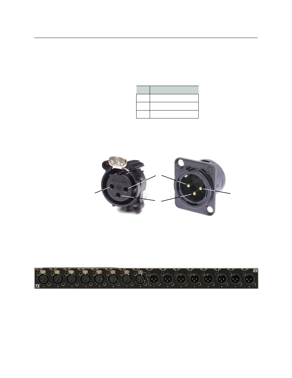
Analog audio I/O is via 3-pin XLR connectors with industry standard wire locations (see
table below). Analog TX and RX modules are in groups of 16 channels.
The XLR connectors are located on the front panel of each module.
• On the input modules, XLR connectors are female Neutrik type NC3FPR-H.
• On the output modules, XLR connectors are male Neutrik type NC3MG-H (refer to
Fig. 2-11: XLR Connectors on TX and RX Modules
Analog TR Modules
Adder II Analog TR modules have eight line level inputs and eight line level outputs as on
the same single module as shown in
Fig. 2-12: Analog TR Module
There are no gain pr phantom adjustments for the 8x8 module. LEDs show AUD Signal
presence and CLIP only.
PIN
SIGNAL
1
Ground
2
Balanced I/O (+)
3
Balanced I/O (-)
2
1
2
3
Input (female)
Output (male)
Line Level Inputs and Outputs