18/+24 audio level reference settings, And in, Table 2-1 – Grass Valley Adder II User Manual
Page 18
14
Setting Up an Adder II System
+18/+24 Audio Level Reference Settings
aggregate data, restores the digital signals and provides switch closures. The number of
data channels is fixed and independent of the number of audio channels in the assembly.
Both data input and output are accomplished on the same connector.
Digital signal connections are made via 9-pin D connectors; see
. The connection
specifications are listed in
; note that these pinots do not conform to standard
serial pinouts and custom cable wiring will typically be required when connecting to third-
party devices. Several interconnection cables are described in
page 28. A 110 Ohm terminating resistor placed across the balanced inputs may be needed
if input cable lengths are in excess of six feet.
Table 2-1: Data pin-outs
Contact closure input is activated by pin 8 on contact to ground or to a TTL logic 0 signal
level. Contact closure output is established by an isolated, normally open, dry contact built
onto the Main PC Board. The eight digital I/O connectors are AMP 747905-2, D-sub female
or equivalent.
Additional data ports can be added in groups of 8 with A2-DATA-8 I/O strips.
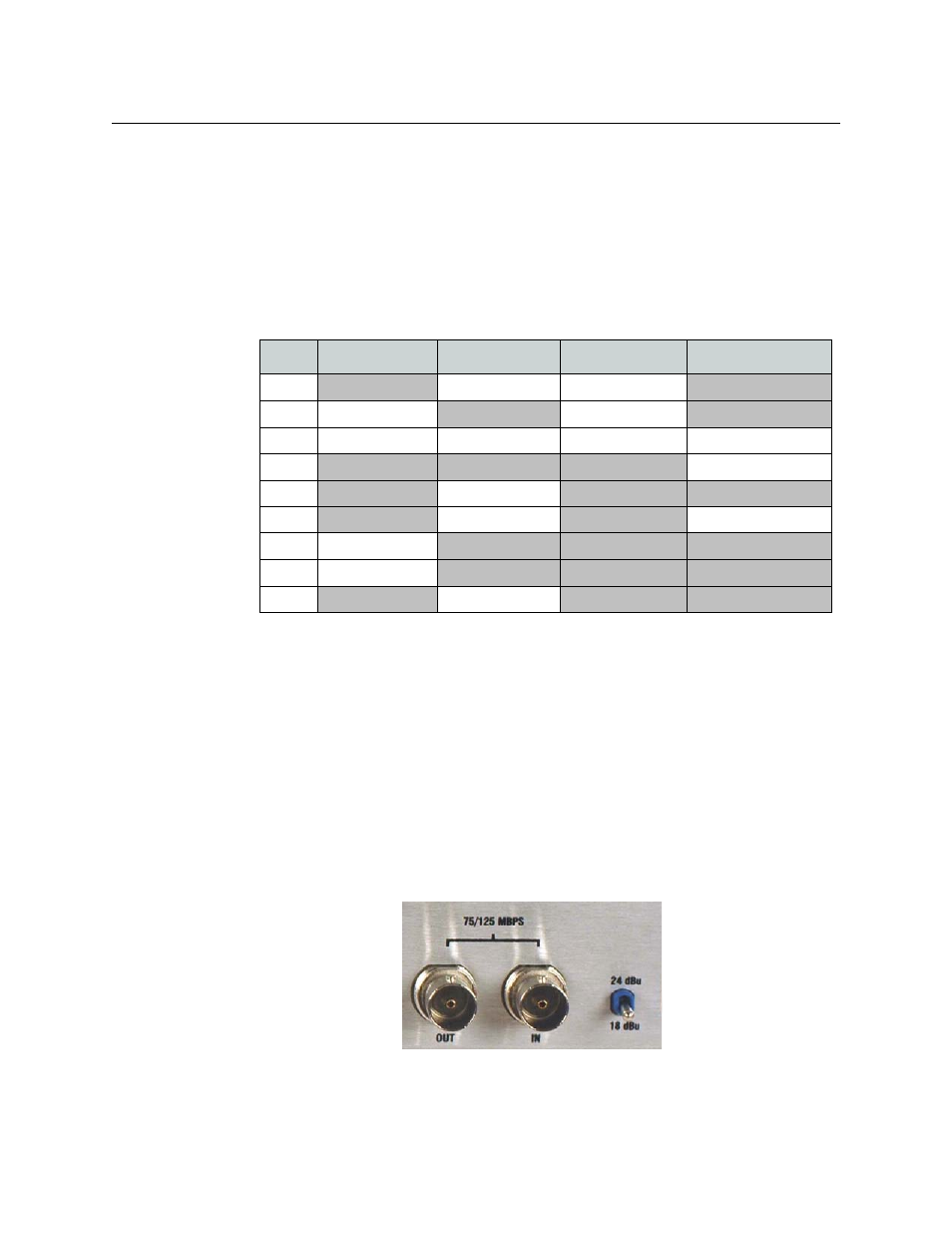
+18/+24 Audio Level Reference Settings
The rear-panel +18/+24 switch toggles the Input analog audio encoder that can be set at
either 18db or 24db. This will determine the level where analog input audio will clip. It is
not necessary that both ends of the link be set the same.
Fig. 2-8: +18/24 Switch Location
PIN
Conns 1 & 2
Conns 3 & 4
Conns 5 & 6
Conns 7 & 8
1
422 TX (-)
485 TX/RX (-)
2
GPI Out (+)
485 TX/RX (+)
3
GND
GND
GND
GND
4
232 RX
5
422 RX (-)
6
422 TX (+)
232 TX
7
GPI Out (-)
8
GPI In (+)
9
422 RX (+)