Selecting channels to modify, Les (see, Local and remote gain – Grass Valley Adder II User Manual
Page 22: Control of analog audio modules
18
Setting Up an Adder II System
Local and Remote Gain Control of Analog Audio Modules
Local and Remote Gain Control of Analog Audio Modules
Analog gains are adjusted via a knob and two buttons on the Base Unit. The following
selection describes procedures for making input adjustments. Control location is indicated
in
. Note that adjustments for an audio path can be set from either end of the
link.
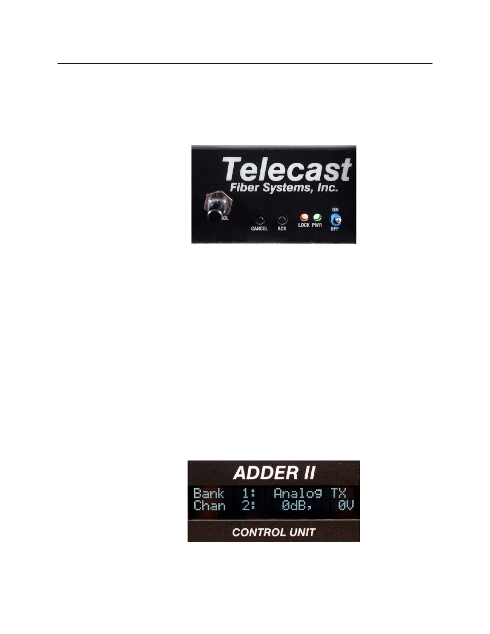
Fig. 2-15: Local gain controller/selector
The process starts by pressing the ACK button and then dialing the control knob indicate
the proper “Bank” or module. All modules except the base and 882i can be addressed. An
attempt to address an audio path that does not contain an analog TX will result in the
message gain ”[FIXED]”. An example of this might be an AES TX connected to an analog RX.
Remember that the Base Control Unit occupies Bank 0, so that the first module up is Bank 1,
the second is Bank 2, etc. Once you have found the analog module that requires
adjustment, press the ACK button to acknowledge that you are in position to select
channels to modify.
You may press the CANCEL button at any time to start the process over from the beginning.
Once you have selected the proper Bank, you can now opt to select one channel or make a
universal change to all of the channels in that Bank.
Selecting Channels to Modify
By using the knob to scroll to Chan:ALL, you can change gain and phantom voltage for all
16 inputs in one step.
shows that the SEL LEDs for all 16 inputs are illuminated
and blinking. LED’s above the channels will remain illuminated to show that a change has
been made from unity gain or no phantom voltage.
Fig. 2-16: Starting point