Power requirements – Grass Valley Adder II User Manual
Page 13
9
Adder II
User Guide
Power Requirements
Adder II Systems are largely “Plug and Play”, but there are several steps that must be
followed to ensure the reliability of your system. Providing reliable DC power and having
properly installed fiber optic cables are critical in maintaining reliable operation.
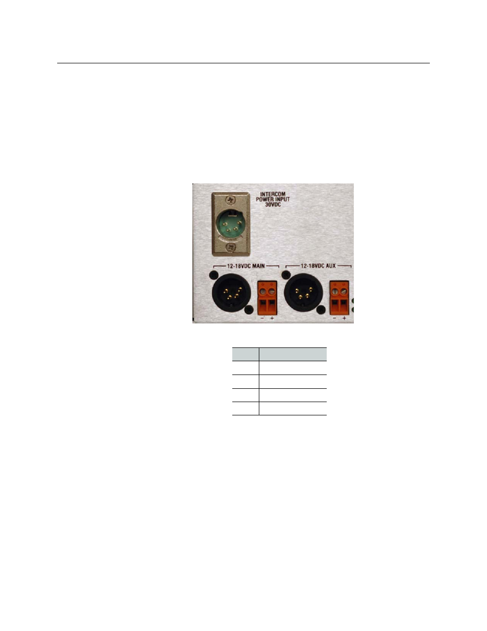
Any power supply used with your Adder II must provide a minimum of 3 amperes,
continuous, at 12 to 18 VDC. Power input is either through two 4-pin XLR-M connectors or
two terminal strips located on the left side of the rear panel that provide for full power
redundancy; see the table below for pinout and
for location. Be sure that AC
outlets are within reach of their six-foot power cords.
Fig. 2-1: Power Input Location
Grass Valley’s ADAP-AC-04 meets the power requirements for Adder II, but any other
suitable DC supply may be used. Note that a fully loaded 125 Mb/sec system (64 bi-
directional channels) can draw up to 5 Amps.
Once power is applied to the rear panel, the front-right mounted switch on the Base unit is
used to “power-on” the system.
• A Green LED near the input XLR’s indicates the presence of DC power.
• ARed LED next to the power switch on the front panel indicates that DC is present.
• A Green LED indicates that power is On.
Frames equipped with an 882i intercom bank will require it’s own 12-18 VDC power
connection to the INTERCOM POWER INPUT 30VDC above the MAIN input. The same wiring
conventions apply.
Pin
Description
Pin 1
Ground
Pin 2
No connection
Pin 3
No connection
Pin 4
+ VDC