Clear-com, Nulling procedure – Grass Valley Adder II User Manual
Page 26
22
Setting Up an Adder II System
Clear-Com
Clear-Com
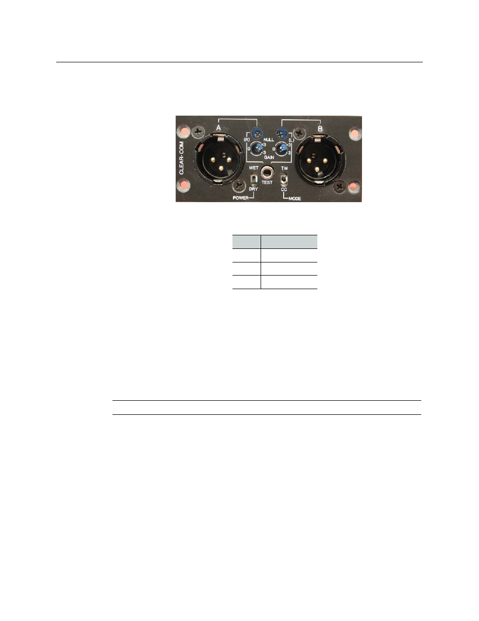
Clear-Com intercom modules have a 3-pin XLR connector for each of the A and B channels.
This Grass Valley module fully supports the Clear-Com signaling protocol and signal levels.
Fig. 2-24: Clear Com module
The Clear-Com Intercom Connections are listed in the table below.
• The units null by plugging in a 1/8-inch (3.5mm) stereo headset (not a TS-1) into the
connector located in the center of the unit and then adjusting the top set of pots for
optimum null.
• The second set of pots, labeled GAIN, adjust the receive gain for that channel +/-3db.
• The POWER switch controls whether 30VDC is applied to beltpacks and/or remote
stations that might be plugged into the module.
• The MODE switch should always be set to CC for Clear-Com intercom systems.
Nulling Procedure
Inserting the 1/8” sub-mini stereo headset jack into the Clear-Com module turns on a tone
that nulls the system. It is important that the nulling procedure be done when all beltbacks
and other interfaces are in place. If you add additional beltpacks, it is likely that the nulling
procedure should be repeated.
As indicated on the module faceplate, the right ear serves Channel A and the left ear serves
Channel B. Do not listen to both ears at the same time as this will not allow you to carefully
discern the tone.
While listening to the right side, turn the adjustment pot on the top left above the mini
headset jack. The goal is to eliminate and/or minimize the nulling tone. Once you have
gotten the adjustment so that the tone is as quiet as possible, then change ears and do
Channel B while using the top right adjustment pot.
Pin
Description
Pin 1
Ground
Pin 2
+VDC Power
Pin 3
Power
Note: A stereo audio headset and a tweeker are needed to null these modules.