Verifying optical link – Grass Valley Adder II User Manual
Page 15
11
Adder II
User Guide
In either scenario, you can make two links and the Adder II will automatically switch links
should one fail. This solution offers complete and automatic optical redundancy (see
Once you choose your method of connection, inspect the fiber ends and clean them with
Kim-Wipes that have been wet with pure isopropyl alcohol. Fingerprints or other dirt on the
optical connector end surfaces will reduce the received optical signal level.
Note that, unlike previous Adder systems, the fiber has priority in the Adder II. This means
that the system will always look for a link on the fiber ports first and then on the coaxial
ports. But also note that the coax path can be used as a redundant path.
Verifying Optical Link
Once both ends are powered up and your fiber connections are made, it becomes a simple
matter to verify how you are connected and the status of your optical link.
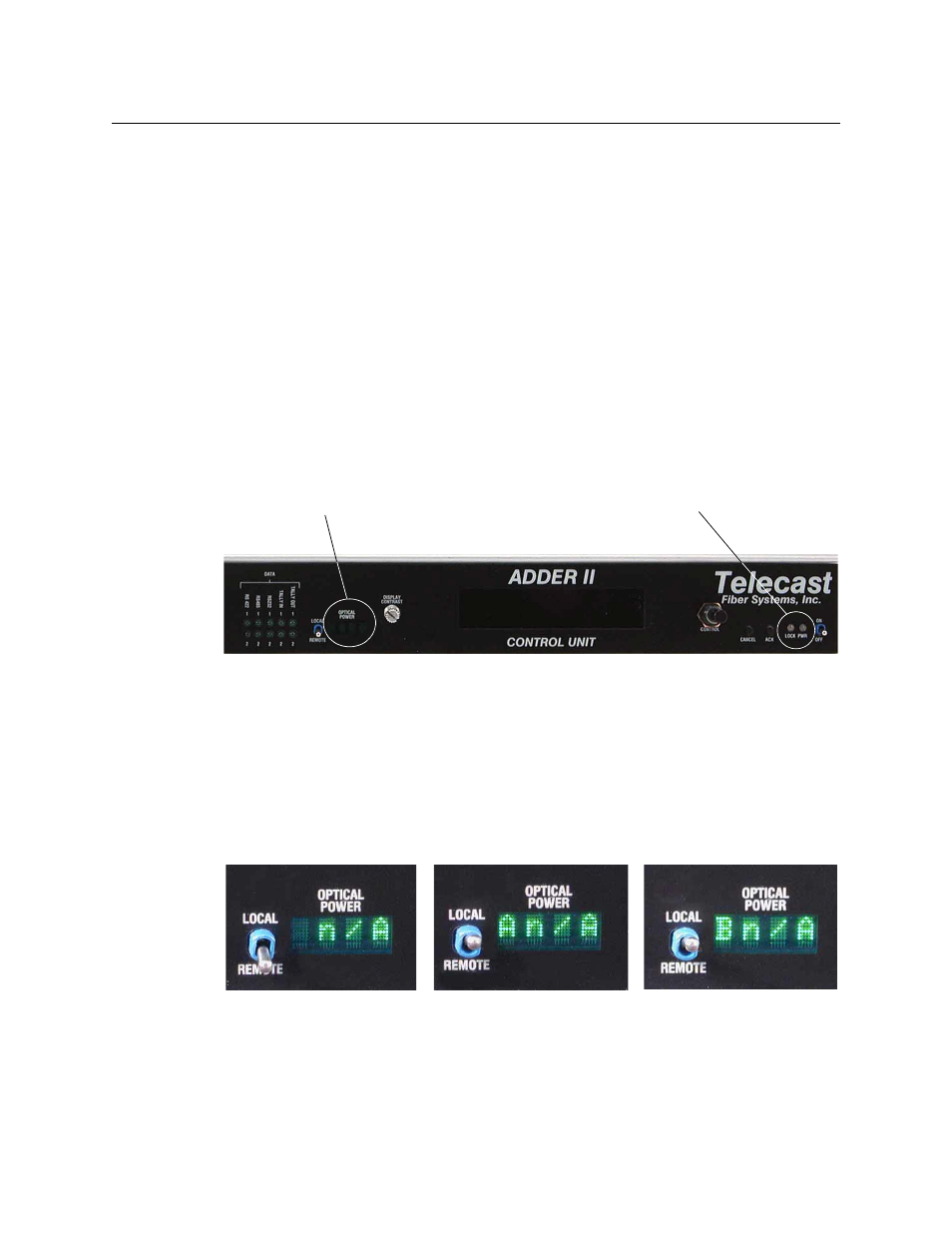
In the center of each Base faceplate there is a 4-Segment display labeled OPTICAL POWER.
The actual location is indicated in
Fig. 2-3: Optical Power Display and LINK LED Location, Front panel
• With the switch to the REMOTE position, the display will indicate the optical power at
the other end of the link if the link is good. Otherwise it will display N/A as shown in
• With the switch in the LOCAL position, the display will indicate both the INPUT that the
frame is linked to and the received optical power in dBm’s. The second two photos, in
, show that the box is looking at both inputs A and B, but that there is no
optical power present. If the link is good, a value for the optical power would be
indicated. An optical power reading between -5 and -22 dBm will be optimal.
Fig. 2-4: Optical Power Display – various conditions
In addition to the optical power readings, a Green LOCK LED on the right side of the Base
faceplate (next to the power switch) indicates that the frame is properly linked. A Red LED
indicates no link/lock (see
).
Optical Power
Display
LINK LED