Setting phantom voltage, Aes 8 tx and rx modules, External aes sync – Grass Valley Adder II User Manual
Page 24
20
Setting Up an Adder II System
Setting Phantom Voltage
Setting Phantom Voltage
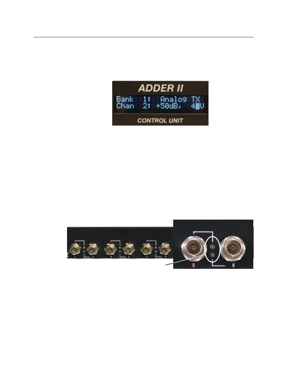
Once the gain change is acknowledged, Volts will flash. Use the control knob to toggle
between the three phantom voltage options: 0V, 12V, and 48V. Once the desired voltage
level is displayed, press the ACK button to set.
shows that we are setting the
phantom power to 48V.
Fig. 2-20: Setting Phantom Voltage
Note that there will be a short delay while the inputs are updated with the new settings.
The Adder II system will remember any gain or phantom settings between power ups.
If a frame is linked to a different frame, the settings from the analog TX modules will be
restored on both ends of the system. The message Synchronizing With Remote Unit will
appear as settings are restored during start-up or following a power or fiber failure. And loss
of link will result in the display of Communication Failure.
The Adder II will remember all settings following a power failure.
AES 8 TX and RX Modules
The TX and RX AES 8-channel modules feature BNC connectors for input and output. A
representative module is shown in
.
Fig. 2-21: AES-8 TX and AES LEDs
Each channel has a single green LED that indicates signal presence. All levels and other
signal parameters are as defined by the AES-3 specification (user bits are NOT maintained).
Modules come in 8 TX and 8 RX.
External AES Sync
Input AES audio is synchronized by local internal clock or can be synchronized to an
external source connected to the BNC connector located on the rear panel. Any AES digital
signal with or without audio (null word okay) can be used for this purpose.
AES LEDs