Signal generator/analyzer – Grass Valley Adder II User Manual
Page 19
15
Adder II
User Guide
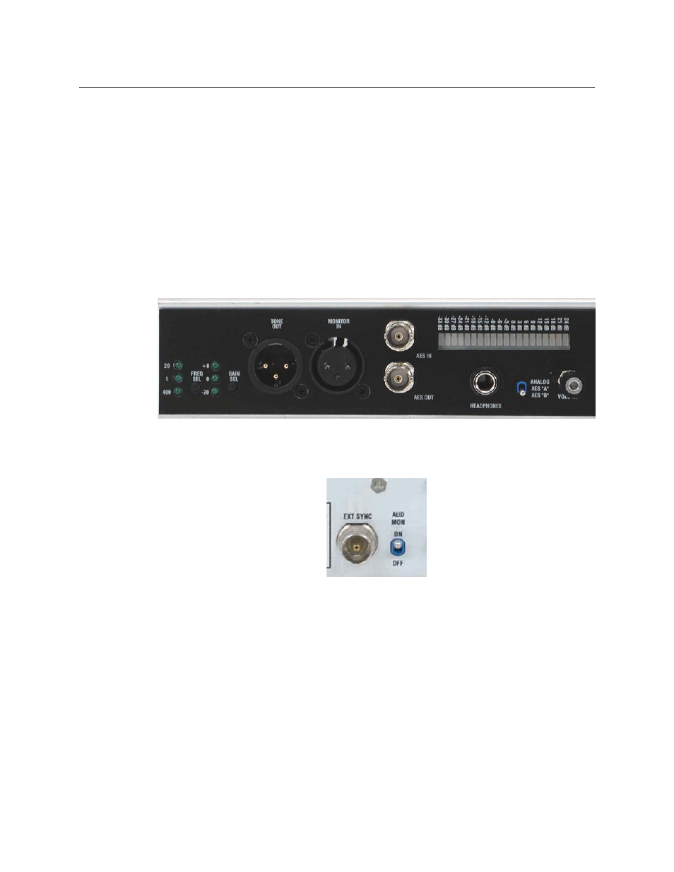
Signal Generator/Analyzer
The integrated audio signal generator/analyzer is a convenient way to confirm signal
presence for both analog and digital (AES) audio signals.
Tone for analog signals is accessed via the XLR-Male connector TONE OUT using standard
XLR audio cable. Three different frequencies (20Hz, 400HZ and 1k Hz) are available at three
different audio levels (-20, 0 and +8 db) to allow easy channel verification/identification.
Selection is via the small buttons on the lower right side of the base unit (see
For digital signals, tone (Line Level @ 1Khz) is available on the AES OUT BNC.
A built-in speaker is accessed via XLR-Female connector MONITOR IN (for analog signals)
using standard XLR audio cable. Digital signals are monitored via the AES IN BNC. The
speaker is directly associated with the audio level bar graph that will indicate audio levels
from -33 to +24 db. Speaker volume is controlled via the VOLUME knob.
Fig. 2-9: Analog/Digital Signal Generator/Analyzer
In order to monitor analog and AES signals properly, payattention to the switch to the left
of the VOLUME knob.
Fig. 2-10: AUD MON On/Off Switch
When monitoring only analog signals, the switch can remain in the top ANALOG position.
For AES signals, A refers to the left component and B to the right component of a given AES
signal. Be sure you are monitoring the correct “side” of your digital signals.
Use of the headphone jack (1/4” standard) automatically disables the external speaker.
There is also a switch on the rear of the frame for disabling the speaker.