Connections, Fiber connections – Grass Valley Adder II User Manual
Page 14
10
Setting Up an Adder II System
Connections
Connections
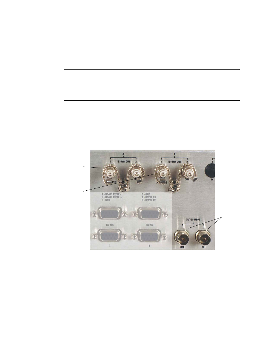
Fiber Connections
An infrared laser diode that is coupled to the fiber generates the optical output from each
TX. User connections are made at bulkhead ST type connector s on the rear panel (see
). You can use either single mode or multimode fiber, but take care to never mix
types of fiber in a given run. Once you employ WDMs into the system, their type will dictate
the type of fiber to use.
The RX inputs use an InGaAs pin diode and amplifier to convert the optical signal back into
an electrical signal.
Fig. 2-2: Fiber and Coax I/O Locations, Rear Panel
There are several ways to configure fiber in your Adder II systems:
• 1310 only: two fibers connect the IN’s of each to the OUT’s of the other in the 1310nm
optical window.
• 1550 only: two fibers connect the IN’s of each to the OUT’s of the other in the 1550nm
optical window.
• 1310 in one direction and 1550 in the other: requires only one fiber per link but
requires the addition of either an internal or an external WDM.
WARNING
:
Never look directly into the unit of a connected optical fiber while any component of
the system is operating. Eye damage is possible.
Use the onboard optical power meter as a means of testing the optical signal at both
ends of your optical link.
1310 NM
Fiber I/O
1550 NM
Fiber I/O
Coaxial
I/O