Frame bus jumpering – Grass Valley 8985FS v.1.3.2 User Manual
Page 17
8985FSP/FS — Instruction Manual
17
Installation
Frame Bus Jumpering
If you will be using this 8985 module to distribute reference Frame Bus 1
(slot 1) or Frame Bus 2 (slot 3), you must set a jumper on the front module
circuit board for this purpose before installing the module (
).
•
Frame Bus 1 – to transmit the reference connected to one of the Genlock
Loop BNCs on the corresponding rear module on Frame Bus 1, set
jumper J10 to
ENA
(pins 1-2). This module must be installed in slot 1 of
the frame and configured on the Genlock web page (see Genlock Web
Page
) for
Auto
in the Drive Frame Reference Bus pulldown.
•
Frame Bus 2 – to transmit the reference connected to one of the Genlock
Loop BNCs on the corresponding rear module on Frame Bus 2, set
jumper J13 to
ENA
(pins 1-2). This module must be installed in slot 3 of
the frame and configured on the Genlock web page (see Genlock Web
Page
) for
Auto
in the Drive Frame Reference Bus pulldown.
Note
Both jumpers may be enabled. The module in slot 1 will only read the status
of jumper, J10. The module in slot 3 will only read the status of jumper, J13.
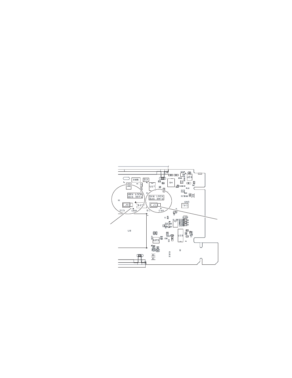
Figure 4. Setting Frame Bus Jumpers
8431_06
For Frame Bus 2 distribution, set
GEN LOCK BUS XMT2 jumper, J13
Pins 1-2 (ENA) or pins 2-3 (DIS).
For Frame Bus 1 distribution, set
GEN LOCK BUS XMT1 jumper, J10
Pins 1-2 (ENA) or pins 2-3 (DIS).
Pin 1 of J10
Pin 1 of J13