Grass Valley LDK 4410 User Manual
Page 75
LDK 4410 + LDK 5420 3G Fiber Transmission System User’s Guide (v1.0)
75
Chapter 6 - Connectors
Reference input / teleprompter output connector
Auxiliary connector
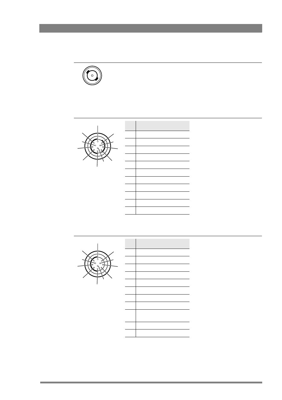
Tracker connector
Reference input (in stand alone mode)
This connector is used to genlock the camera to a 0.6 Vpp HD tri-level reference
input signal.
Teleprompter output (when the base station is connected)
This socket supplies the 1.0 Vpp teleprompter video signal coming from the base
station.
BNC connector
5
10
6
1
7
8
2
9
11
3
4
Pin Description
1
+5 VL
2
0 VL
3
AN0
4
AN1
5
Not connected
6
On Air / Not connected
7
Private Data (Cam to BS)
8
GND
9
Private Data (BS to Cam)
10
GND
11
Shield
Fischer 11-pin female
Private data input signals:
“0” < 4.0 V; “1” > 4.0 V
max. level: +/-12 V
input impedance: > 4.7 k
bitrate: max. 100 kbit/s
Private data output signals:
CMOS levels +5 V
output impedance: 250
Analog outputs (AN0 and AN1):
output level: 0 to +5 V
output impedance: 100
5
10
6
1
7
8
2
9
11
3
4
Pin Description
1
On Air return
2
Tracker microphone return
3
Tracker microphone input
4
Production tracker
5
Sidetone/engineering tracker
6
Intercom return
7
Program sound tracker
8
Cameraman microphone
9
Tally control tracker (CMOS
level, R
out
= 1 k
)
10
12 V (I
max
= 100 mA)
11
12 V return
Mic. level: -64 dBu/-24 dBu switchable
Mic. impedance: > 600
Intercom output level: 0 dBu (nom.),
+6 dBu (max.)
Intercom output impedance: < 200
Fischer 11-pin female