Chapter 6 - connectors, Pin description – Grass Valley LDK 4410 User Manual
Page 67
LDK 4410 + LDK 5420 3G Fiber Transmission System User’s Guide (v1.0)
67
Chapter 6 - Connectors
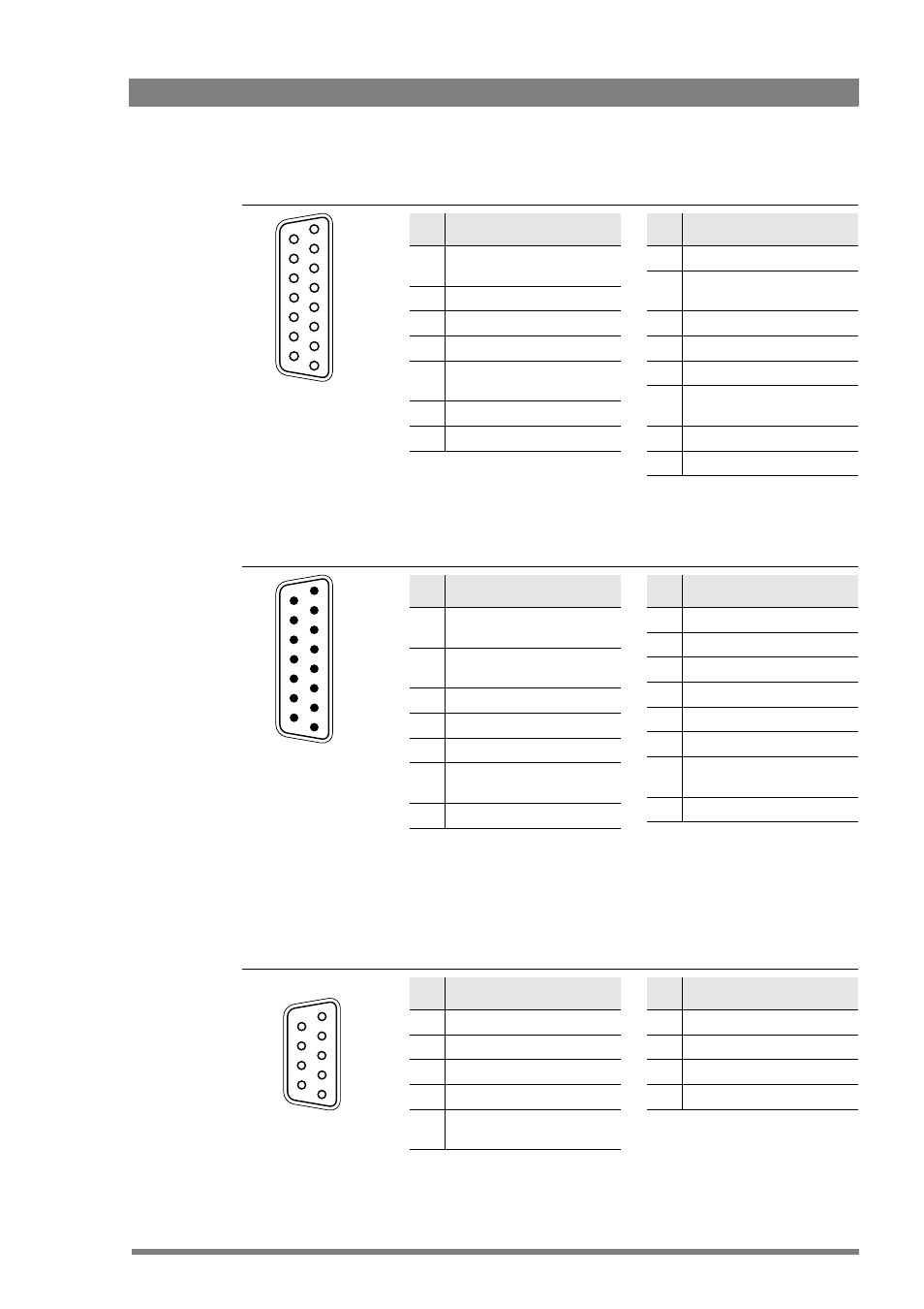
Intercom connector
Signalling connector
Auxiliary connector
Pin Description
1
Prod out (4-wire out, 2-wire
in/out)
2
Prod in (4-wire only)
3
Prod in shield (4-wire only)
4
Eng in (4-wire only)
5
Eng out (4-wire out, 2-wire in/
out)
6
Prog in (4-wire only)
7
Prog in shield (4-wire only)
Shield of cable to the pin marked housing.
5
8
7
6
4
3
2
1
15
14
13
12
11
10
9
SubD 15-pin female
Pin Description
8
Housing
9
Prod out return (4-wire out, 2-
wire in/out)
10
Prod in return (4-wire only)
11
Eng in shield (4-wire only)
12
Eng in return (4-wire only)
13
Eng out return (4-wire out, 2-
wire in/out)
14
Prog in return (4-wire only)
15
Housing
Pin Description
1
Preview output ext. (relay
contact < 10
)
2
Call output ext. (relay contact
< 10
)
3
ISO input ext. (dry contact)
4
On Air input ext. (dry contact)
5
Call input ext. (dry contact)
6
Audio 1 level (analog input
voltage from 0 to 5 V)
7
5 V (Operating Control Panel)
Microphone impedance >200
Sensitivity range: -70 to -28 dBm
Signal at pin 2 of audio input is in phase with signal at pin 2 of the audio output.
Shield of cable to the pin marked housing.
4
1
2
3
5
6
7
8
9
10
11
12
13
14
15
SubD 15-pin male
Pin Description
8
Housing
9
Preview output ext. return
10
Call output ext. return
11
ISO input ext. return
12
On Air input ext. return
13
Call input ext. return
14
Audio 2 level (analog input
voltage from 0 to 5 V)
15
GND
Pin Description
1
5 V
2
AN0 (0 to 5 V input)
3
Private data out
4
Private data in
5
Housing (attach cable shield
to this pin)
SubD 9-pin female
connector
Shield of cable directly to the connector housing.
5
4
3
2
1
9
8
7
6
Pin Description
6
GND
7
AN1 (0 to 5 V input)
8
Private data out return
9
Private data in return