Module repair, Functional description, Input processing – Grass Valley 2031RDA-MM User Manual
Page 34: Alley (see
34
2031RDA-SM/-MM Instruction Manual
Functional Description
Module Repair
If the module is still not operating correctly, replace it with a known good
spare and return the faulty module to a designated Grass Valley repair
depot. Call your Grass Valley representative for depot location.
at the front of this document for the Grass
Valley Customer Service Information number.
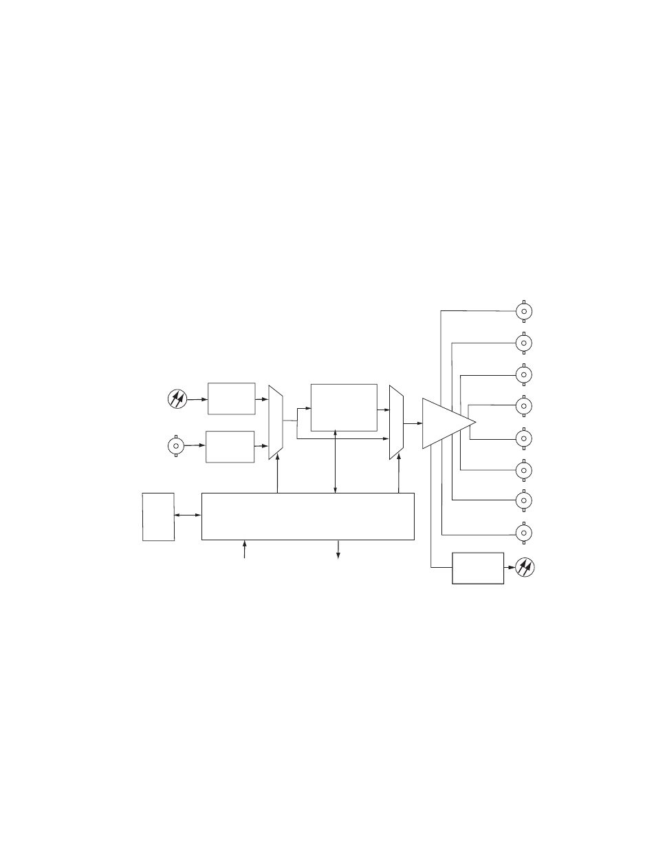
Functional Description
A block diagram of the 2031RDA-SM/-MM is shown in
Figure 17. 2031RDA-SM/-MM Block Diagram
Input Processing
The wideband serial SD signal enters the module from rear BNC J10
(labeled In) to an input amplifier. It is then equalized for the specified cable
lengths in the equalizer circuit.
8318_06
Microprocessor
J1
J7
J5
J6
J3
J4
J9
8
Electrical
Coax
Outputs
J8
Bypass
Front
LEDs
On-board
Jumpers
Reclocker
Optical
Receiver
Equalizer
2000
Frame
Bus
Optical
Transceiver
Optical
Output
Optical
Input
Coax
Input