Grass Valley 2031RDA-MM User Manual
Page 20
20
2031RDA-SM/-MM Instruction Manual
Configuration and Monitoring
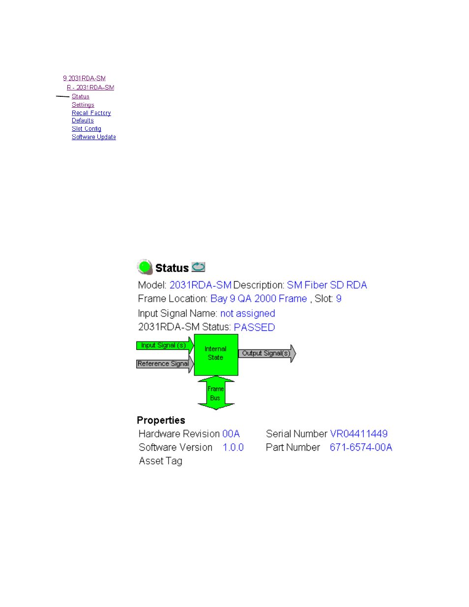
Status Web Page
The Status web page shows the status of the input signal(s) and the frame
bus communication. Color coding of the display indicates the signal status.
In general, colors used on the frame and modules indicate:
•
Green – normal operation, (Pass) or signal present, module locked.
•
Red – On continuously = fault condition, flashing = internal error.
•
Yellow – On continuously = active condition (configuration mode or
communication), flashing in sequence = module locator function.
•
Grey – not monitored, such as the Reference Signal and the Output
Signal(s) for this module.
Information about the module, such as part number, serial number, hard-
ware revision and software version, and Asset Tag number are given in a
read-only
Properties
section at the bottom of the display.
The Status page for the 2031RDA-SM is illustrated in
Figure 10. 2031RDA-SM Status Web Page
Use
this
link