Power up, Operation indicator leds – Grass Valley 2031RDA-MM User Manual
Page 11
2031RDA-SM/-MM Instruction Manual
11
Power Up
Power Up
The on-board LED indicators are illustrated in
power-up, the green PWR LED should light and the yellow CONF LED
should illuminate for the duration of module initialization.
Operation Indicator LEDs
With a valid input signal connected, the green on-board PWR LED and the
SIG LED (visible from the rear) should be on. A red FAULT LED indicates
an error situation and, when noted with the other indicator LEDs, can indi-
cate a specific problem area.
describes signal output and LED indi-
cations for the various combinations.
provides the possible input and output conditions that result from
different input signals and conditions.
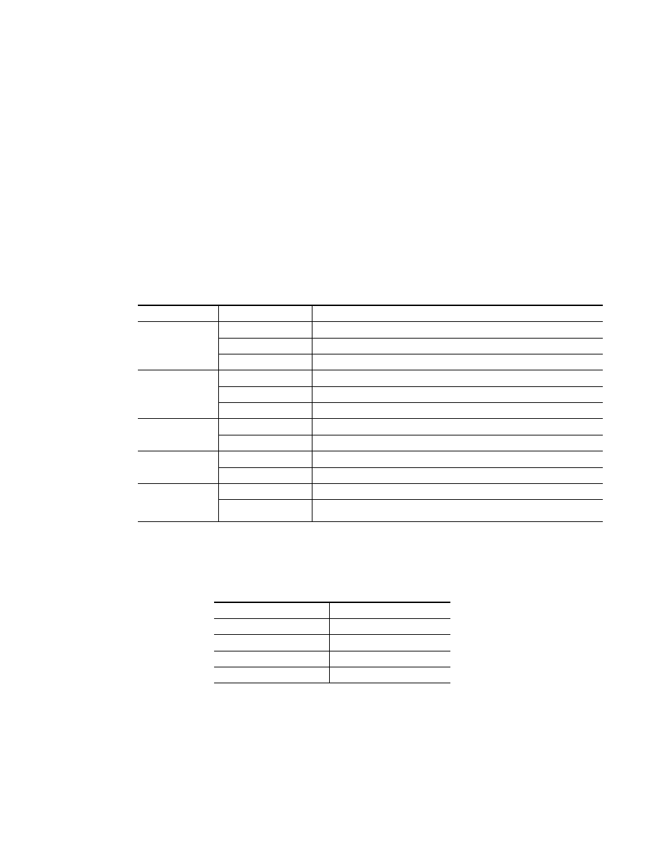
Table 1. Indicator LEDs and Conditions Indicated
LED
Indication
Condition
FAULT
(red)
Off Normal
operation
On continuously
Module has detected internal fault.
Long flash
No input signal or input signal does not meet selected standard.
COMM
(yellow)
Off
No activity on frame communication bus.
Long flash
Location command received by the module from a remote control system.
Short flash
Activity present on the frame communication bus.
CONF
(yellow)
Off
Module is in normal operating mode.
Short flash
Module is initializing, changing operating modes or updating firmware.
PWR
(green)
Off
No power to module or module’s DC/DC converter failed.
On
Normal operation, module is powered.
SIG PRES
(green on rear
of module)
Off
Carrier input signal is present at either the coax or fiber optic input.
On
No carrier input signal is present at either the coax or fiber optic input.
Table 2. Input and Output Conditions
Input Condition
Output Condition
Serial Digital Component (SDI)
Serial Digital Component (SDI)
Other carrier
Other carrier
No input
Muted
Cable exceeding 200 meters
Muted