Multiple vrrp groups configuration example, Network requirements, Configuration procedure – H3C Technologies H3C S6800 Series Switches User Manual
Page 44
36
Multiple VRRP groups configuration example
This section provides an example of configuring multiple VRRP groups on switches.
Network requirements
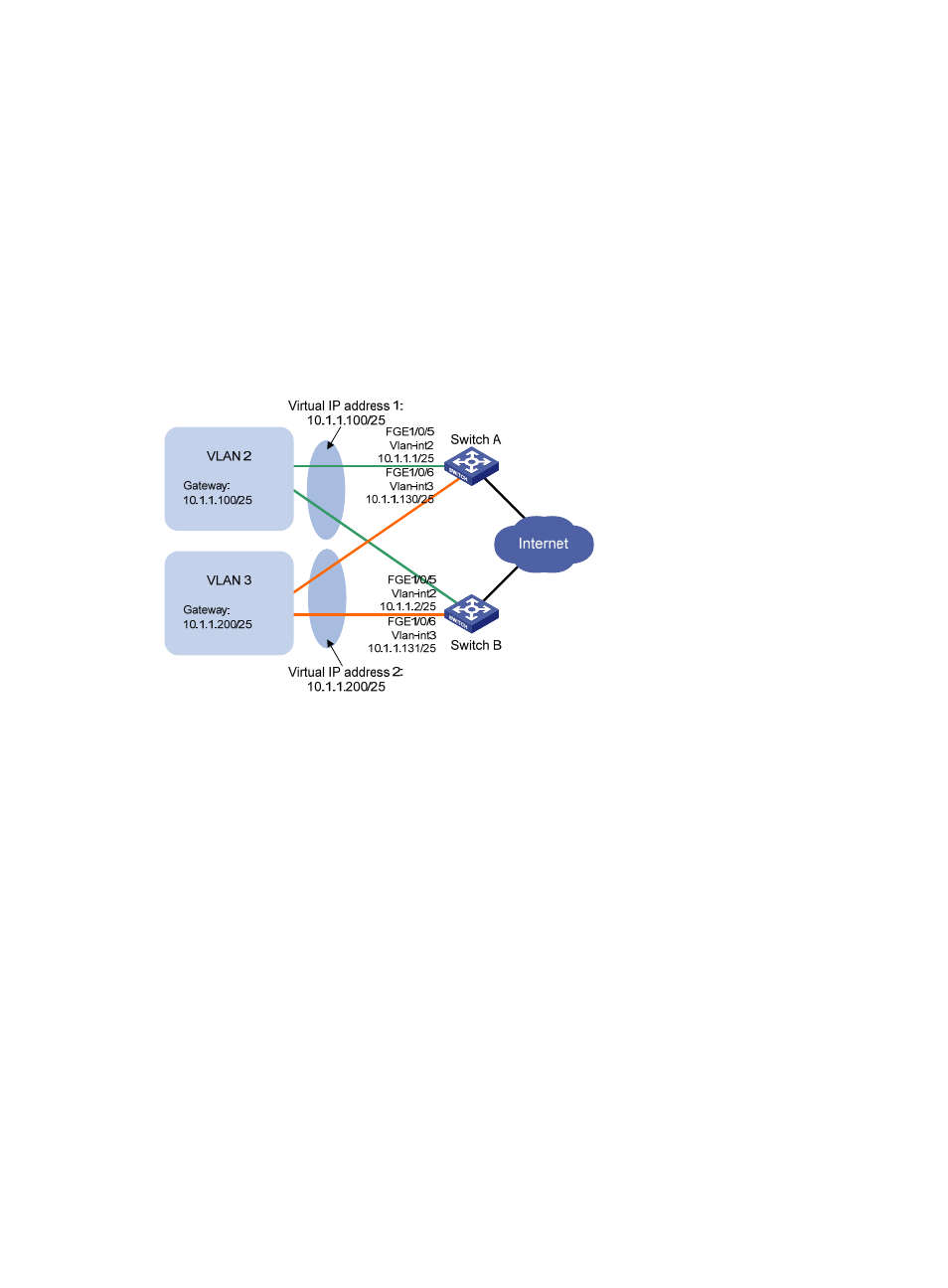
Switch A and Switch B form two VRRP groups. VRRP group 1 uses the virtual IP address 10.1.1.100/25 to
provide gateway service for hosts in VLAN 2, and VRRP group 2 uses the virtual IP address
10.1.1.200/25 to provide gateway service for hosts in VLAN 3, as shown in
.
Assign a higher priority to Switch A than Switch B in VRRP group 1, but a lower priority in VRRP group
2, to distribute the traffic from VLAN 2 and VLAN 3 between the two switches. When one of the switches
fails, the healthy switch provides gateway service for both VLANs.
Figure 16 Network diagram
Configuration procedure
1.
Configure Switch A:
# Configure VLAN 2.
[SwitchA] vlan 2
[SwitchA-vlan2] port fortygige 1/0/5
[SwitchA-vlan2] quit
[SwitchA] interface vlan-interface 2
[SwitchA-Vlan-interface2] ip address 10.1.1.1 255.255.255.128
# Create VRRP group 1, and set its virtual IP address to 10.1.1.100.
[SwitchA-Vlan-interface2] vrrp vrid 1 virtual-ip 10.1.1.100
# Assign Switch A a higher priority than Switch B in VRRP group 1, so Switch A can become the
master in the group.
[SwitchA-Vlan-interface2] vrrp vrid 1 priority 110
[SwitchA-Vlan-interface2] quit
# Configure VLAN 3.
[SwitchA] vlan 3
[SwitchA-vlan3] port fortygige 1/0/6
[SwitchA-vlan3] quit