ACTi I93 User Manual
Page 38
Hardware Manual
Typical Connection
The table below shows the DI/DO connection specifications:
Device
DI
Connection design
TTL - compatible logic levels
Voltage
To trigger (low)
Logic level 0: 0V ~ 0.4V
Normal (high)
Logic level 1: 3.1V ~ 30V
Current
10mA ~ 100mA
DO
Connection design
Transistor (Open Collector)
Voltage & Current
< 24V DC, < 50mA
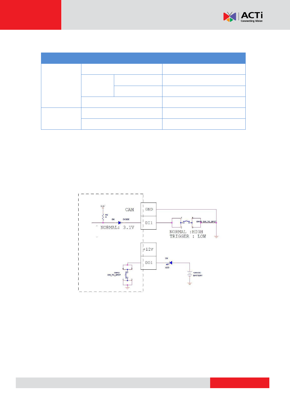
Based on these specifications, if the DI device has a voltage of 0V ~ 30V or the DO device has a
voltage of < 24V (< 50mA), then the camera can supply internal power to these devices and there
is no need to connect the DI/DO device to an external power source.
In this case, use the GND (Black) and the DI1 (Orange) cables to connect a DI device and use
the 12V (Red) and the DO1 (Yellow) cables to connect a DO device. See wiring scheme below:
- I94 I95 I96 I910 KCM-8211 I96 2 MP Extreme WDR Day & Night HPoE Outdoor Speed Dome PTZ IP Camera with 30x Lens I915 2MP Outdoor PTZ Network Dome Camera with Night Vision & Heater B928 5MP Outdoor PTZ Network Speed Dome Camera with Night Vision B915 3MP Outdoor PTZ Network Speed Dome Camera with Night Vision