Connecting di/do device on i910 – ACTi I93 User Manual
Page 37
Hardware Manual
Connecting DI/DO Device on I910
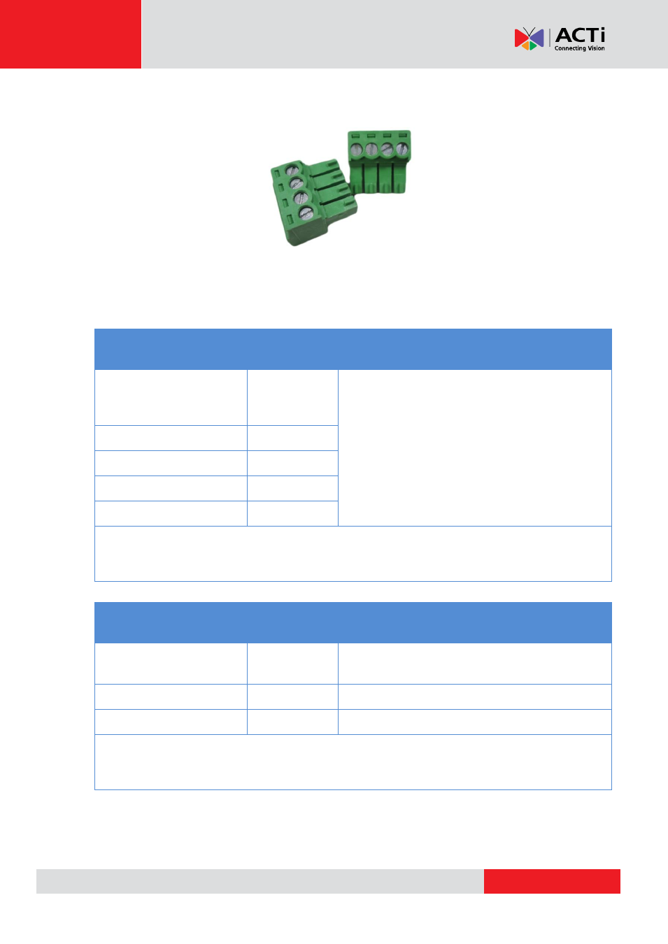
I910 comes with two (2) terminal blocks to connect DI/DO devices.
Map the pins according to one of the pin combinations on the table below. Loosen the screw and
insert the wire through the pin slot on the terminal block, then tighten the screw to secure the wire.
Connect the terminal block(2) to the corresponding cable connector(s).
Device Cable
Terminal
Block Pin
Mapping Instructions
Ground Pin
GND
To connect digital input devices, map the DI
device wires to the following:
Digital Input 1
DI1
DI1
and
GND
Digital Input 2
DI2
DI2
and
GND
Digital Input 3
DI3
DI3
and
GND
Digital Input 4
DI4
DI4
and
GND
NOTE:
In case of connecting more than one DI device, the
GND
pin can be commonly
shared by all four (4) DI devices.
Device Cable
Terminal
Block Pin
Mapping Instructions
DC 12V
12V
To connect digital output devices, map the
DO device wires to the following:
Digital Output 1
DO1
DO1
and
12V
Digital Output 2
DO2
DO2
and
12V
NOTE:
In case of connecting two (2) DO devices, the
12V
pin can be commonly
shared by the two (2) DO devices.
- I94 I95 I96 I910 KCM-8211 I96 2 MP Extreme WDR Day & Night HPoE Outdoor Speed Dome PTZ IP Camera with 30x Lens I915 2MP Outdoor PTZ Network Dome Camera with Night Vision & Heater B928 5MP Outdoor PTZ Network Speed Dome Camera with Night Vision B915 3MP Outdoor PTZ Network Speed Dome Camera with Night Vision