Hakko MONITOUCH V7 series User Manual
Page 342
5
29. Automationdirect PLC
5-135
Co
nne
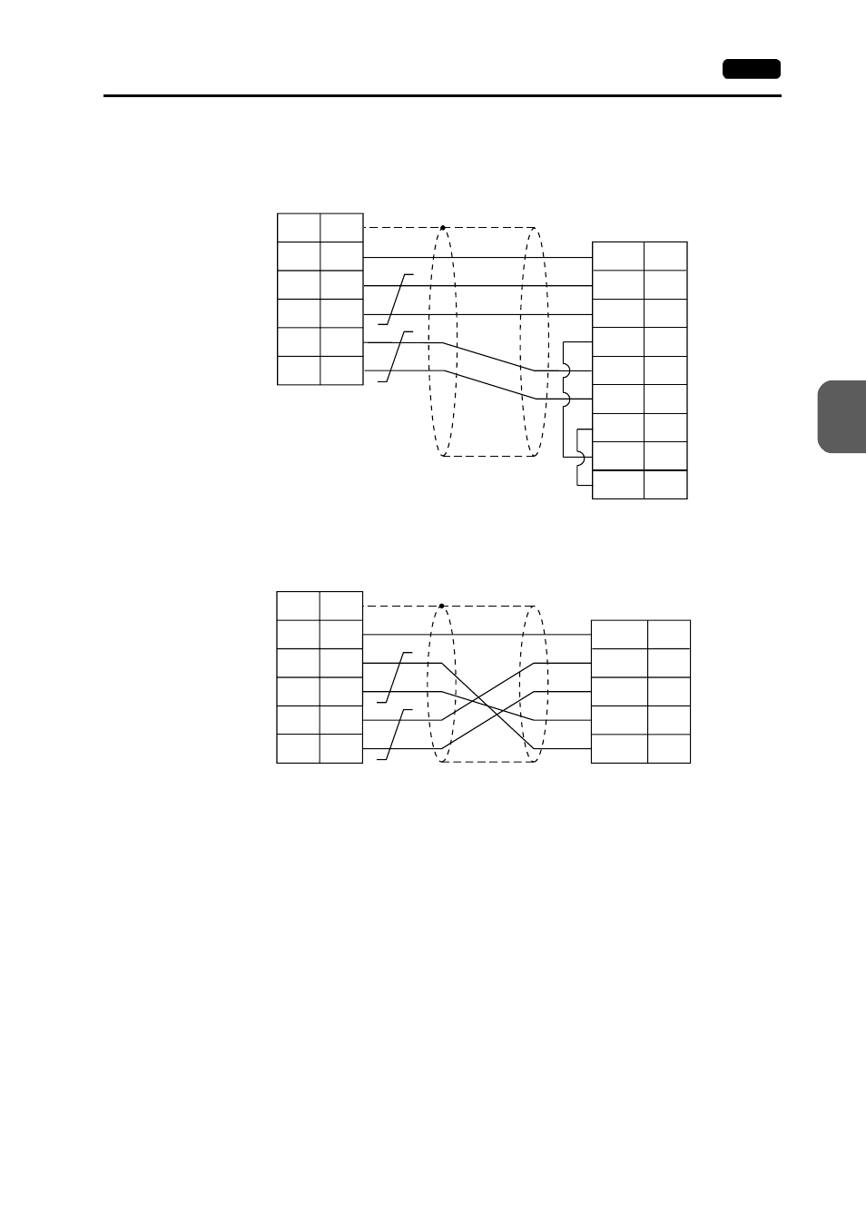
RS-422
Wiring Diagram 5
Wiring Diagram 6
V7 (CN1)
FG
+SD
−
SD
+RD
−
RD
1
12
13
24
25
RXD+
RXD
−
PLC
CTS1+
TXD1+
TXD1
−
RTS1+
RTS1
−
CTS1+
9
10
11
14
16
18
19
23
SG
7
SG
7
* Use shielded twist-pair cables.
D-sub 25-pin (male)
D-sub 25-pin (male)
V7 (CN1)
FG
+SD
−
SD
+RD
−
RD
1
12
13
24
25
TXD3+
TXD3
−
PLC
RXD3+
RXD3
−
12
13
24
25
SG
7
SG
7
* Use shielded twist-pair cables.
D-sub 25-pin (male)
D-sub 25-pin (male)
In case SU-6M, it is possible
to use terminal blocks,