Wiring, Wiring -33 – Hakko MONITOUCH V7 series User Manual
Page 240
5
3. SHARP PLC
5-33
Co
nne
Wiring
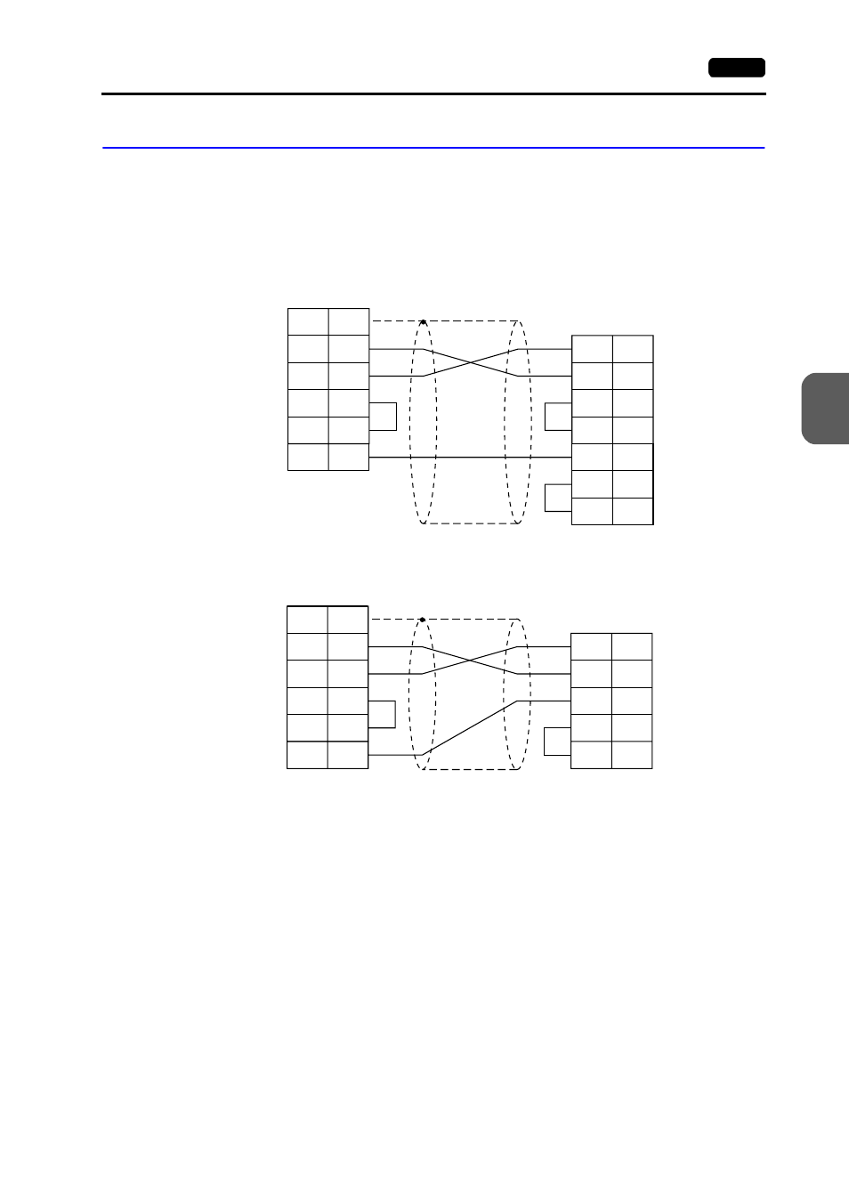
Wiring diagrams with the PLC are shown below.
RS-232C
Wiring Diagram 1
Wiring Diagram 2
FG
RS
CS
SG
1
4
5
7
SXD
RXD
CTS
2
3
5
V7 (CN1)
D-sub 25pin(Male: )
RD
3
RTS
4
PLC
D-sub 15pin(Male: )
SD
2
SG
7
12
14
* Use shielded twist-pair cables.
D-sub 25-pin (male)
D-sub 15-pin (male)
* Use shielded twist-pair cables.
FG
RD
RS
CS
SG
1
3
4
5
7
SD
RD
RTS
2
4
8
V7 (CN1)
D-sub 25pin(Male: )
SD
2
SG
7
PLC
D-sub 15pin(Male: )
CTS
12
D-sub 25-pin (male)
D-sub 15-pin (male)