Terminating resistance setting, Ser ial comm uni c a ti ons – Hakko MONITOUCH V7 series User Manual
Page 110
3
3. n : 1 Connection (Multi-link 2)
3-13
Ser
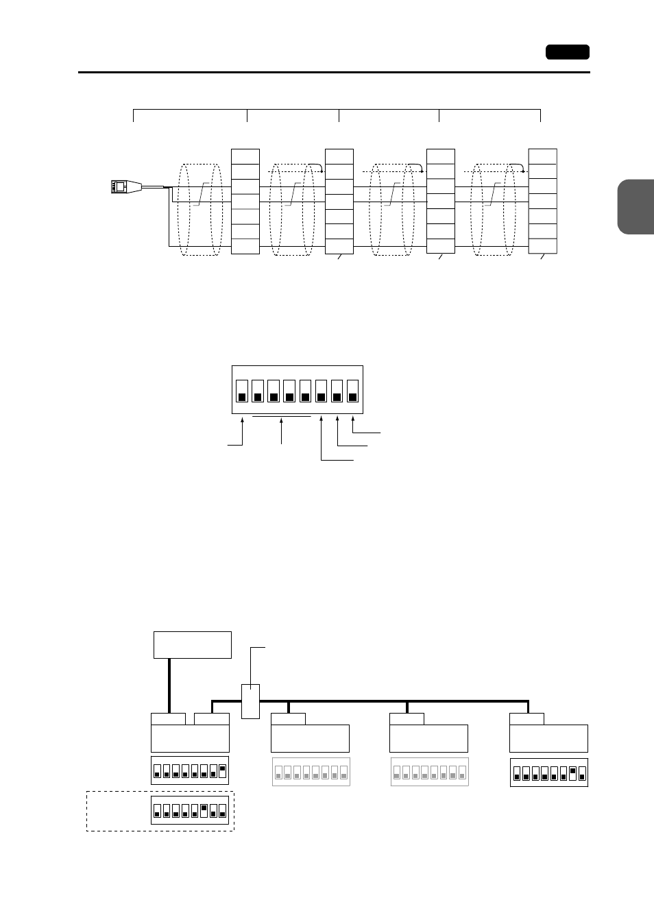
Terminating Resistance Setting
• The terminating resistance of the V7 series should be set on the DIP switch.
• When the PLC and the master station are connected via RS-422/485, set the
terminating resistance at the PLC and the master station (CN1).
• When the V7 series (master and slave stations) are connected via RS-485 (2-wire), set
the terminating resistance at the V7 series master station (MJ1/2) and the terminating
slave station (CN1).
Terminating Resistance Setting Example
1. When the PLC is connected to V7 series master station via RS-232C:
(b)
(c)
(d)
(e)
FG
+SD
-SD
+RD
-RD
SG
SG
SG
+
-
+
-
FG
+SD
-SD
+RD
-RD
SG
FG
+SD
-SD
+RD
-RD
SG
Signal
Name
To be installed by the user
Terminal block
V7 slave station
CN1+TC485
V7 slave station
CN1+TC485
V7 slave station
CN1+TC485
V7 master
station MJ1/2
Terminating
resistance
(OFF)
Terminating
resistance
(OFF)
Terminating
resistance
(OFF)
Terminating
resistance
(ON)
Signal
Name
Signal
Name
Signal
Name
ON
1
2
3
4
5
6
7
8
CF auto load
MJ2 (modular jack 2) terminating resistance
Not used
CN1 RD terminating resistance at pins 24 and 25
MJ1 (modular jack 1) terminating resistance
RS-232C
ON
1
2
3
4
5
6
7
8
ON
1
2
3
4
5
6
7
8
ON
1
2
3
4
5
6
7
8
ON
1
2
3
4
5
6
7
8
ON
1
2
3
4
5
6
7
8
PLC
CN1
CN1
CN1
CN1
MJ1/2
RS-485 (2-wire)
V7 master station
(= Local Port 1)
V7 slave station
(= Local Port 2)
V7 slave station
(= Local Port 3)
V7 slave station
(= Local Port 4)
Terminal block
When MJ1 is
used:
When MJ2 is
used: