Terminating resistance setting – Hakko MONITOUCH V7 series User Manual
Page 131
3-34
7. PLC2Way
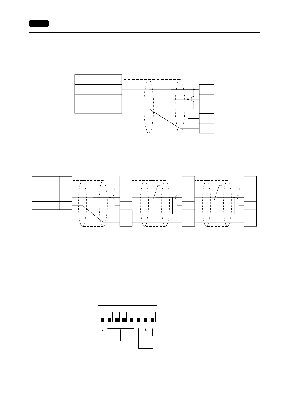
• Connection example with MITSUBISHI A1SJ71UC24-R4 (1 set)
• Connection example with MITSUBISHI A1SJ71UC24-R4 (3 set)
Terminating Resistance Setting
• The terminating resistance of the V7 series should be set on the DIP switch in the
backside of the unit.
• When MJ1 is used: Set DIPSW6 to the ON position.
When MJ2 is used: Set DIPSW8 to the ON position.
PLC
FG
SG
+SD/RD
-SD/RD
5
1
2
SDA
SDB
SG
RDB
RDA
* Use the shielded cable.
V7 series
Modular jack, 8-pin
(Black)
(Green)
(Red)
PLC
FG
SG
+SD/RD
-SD/RD
5
1
2
SDA
FG
SDB
SG
RDB
RDA
PLC
SDA
FG
SDB
SG
RDB
RDA
PLC
SDA
FG
SDB
SG
RDB
RDA
* Use the shielded
cable.
V7 series
Modular jack, 8-pin
(Black)
(Green)
(Red)
Terminating
resistance
(ON)
* Use shielded
twist-pair cables.
Terminating
resistance
(OFF)
* Use shielded
twist-pair cables.
Terminating
resistance
(ON)
Terminating
resistance
(ON)
ON
1
2
3
4
5
6
7
8
CF auto load
MJ2 (modular jack 2) terminating resistance
Not used
CN1 RD terminating resistance at pins 24 and 25
MJ1 (modular jack 1) terminating resistance