Verilink DCSU 2911 (880-502647-001) Product Manual User Manual
Page 17
DCSU 2911 Quick Set-Up
Verilink DCSU 2911 User Manual
2-3
3. From the DCSU Main Menu, select the following:
ACE Controller Menu>
O) ACE Controller Administration Menu>
B) Change ACP Bus
4. Once the bus assignment has been made, reboot the
reassigned module by either
• Using the
Reset
Reset
Reset
Reset command from the ACE Controller
Administration Menu, option R, or
• Reseating the module in its slot.
5. Reconnect to the NCM Local port.
6. Log in. You should now see both modules on the Node Map.
From the NCM Main Menu, select the DCSU application module
using option S, Shelf/Slot. The Main Menu (
) uses
brackets to enclose the U, indicating the DCSU.
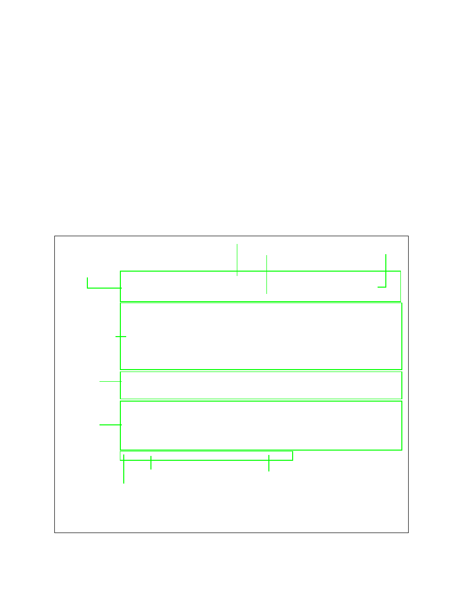
Figure 2-2 NCM Main Menu
-- VERILINK NCM CONTROLLER : FW Rev 4.15, Dec 13 1997 12:53:30 --
Site Name: Verilink Test Access Level: 2
Managing at NEAR end node [127.255.255.0] Node ID: 0
<- SLOT ->
SHELF 1 2 3 4 5 6 7 8 9 10 11 12 13
0 - - - - - - - - - - - - -
1 D *N [U]
2 - - - - - - - - - - - - -
3 - - - - - - - - - - - - -
4 - - - - - - - - - - - - -
KEY: A=DIDCSU, B=DIU/DBU, C=CSU, D=DIU, E=SDIU, F=DIU/DDS, G=DHDM,
H=ATM/IMUX, I=IDCSU, J=PEP, K=DAC, L=HLM, M=IMUX, N=NCM,
Q=QUAD, R=SUBRATE, S=HSM, T=HDM, U=DCSU, V=VCU, X=QPRI
S) shelf/slot O) administration
C) configuration D) diagnostics
P) performance/status A) alarm
B) circuit manager I) manufacturing info
X) exit this screen
A [127.255.255.0] [1,2] DCSU 2911 >
Menu Heading Area
Node “Map” (Physical
Location of Modules)
Command List
Firmware Version and Date of Release
Access Level (1-4)
Node Address
Node Address
Data (Command) Entry Area
Module Key
Active NCM Master Designator
❷
❸
❶
❷
❸
❶
Asterisk indicates that the NCM is the Main Controller in the shelf
Indicator for the type of shelf: M= Multi-line, D = Dual-line
Brackets around module letter ( [U] ) indicate current module selected