Dcsu 2911 front module, Dcsu 2911 front module -2, Leds -2 management ports -2 – Verilink DCSU 2911 (880-502647-001) Product Manual User Manual
Page 10: Leds, Management ports
DCSU 2911 Dual Channel Service Unit
1-2
Verilink DCSU 2911 User Manual
DCSU 2911 Front
Module
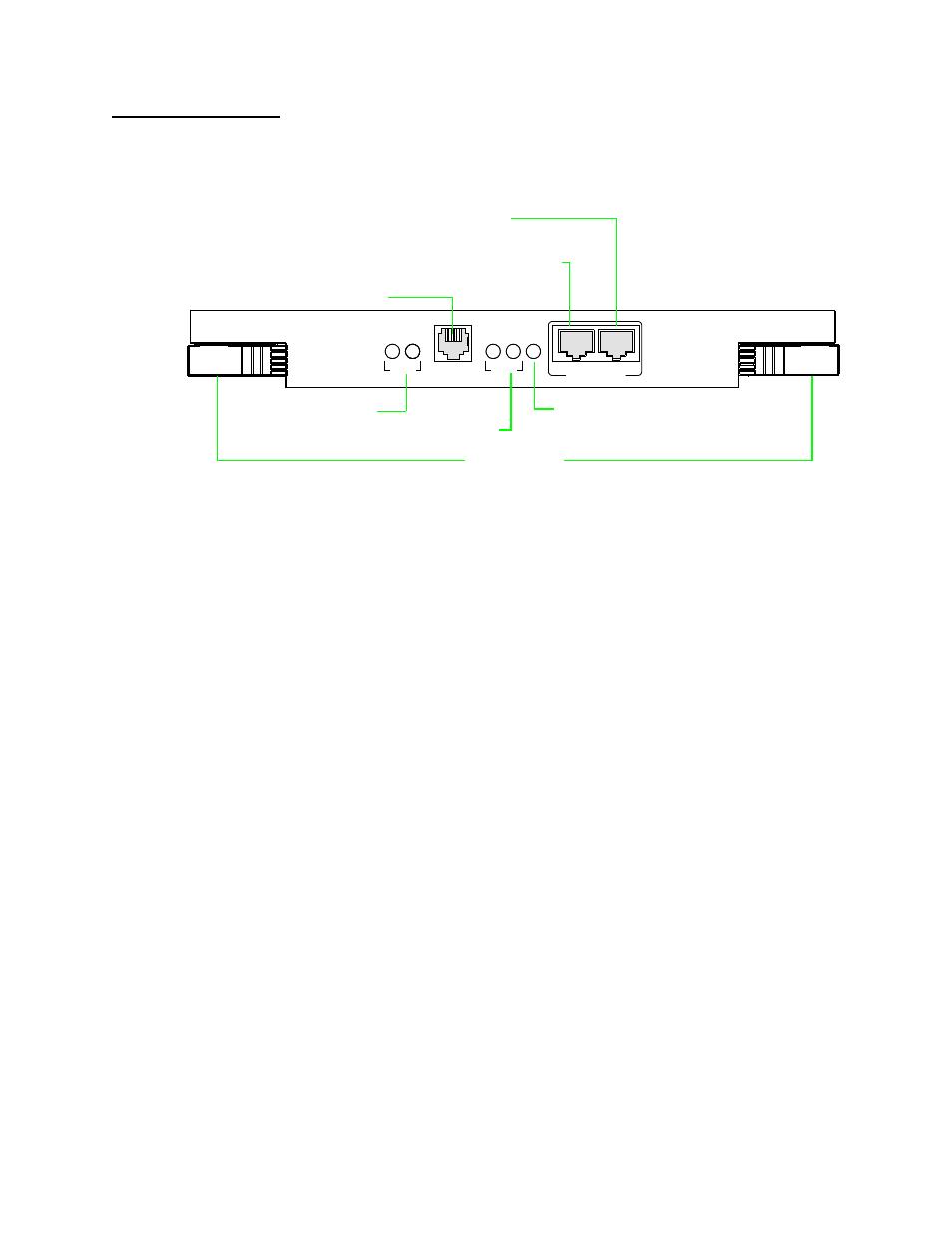
Figure 1-2 shows the DCSU 2911 front panel.
Figure 1-2 DCSU 2911 Front Panel
LEDs
The DCSU front panel’s System LED (SYS) is green when the module
has passed the power-up self-test.
The panel also contains four status LEDs:
•
Two for network port status (T1 or E1)
•
Two for customer provided equipment (CPE) port status
Chapter 4 of this manual defines the LEDs and alarms.
Management Ports
Three front panel management ports are provided:
•
Local—RJ-11 (6-pin, RS-232-compliant) Craft interface for
connecting an ASCII terminal, a PC running a terminal
emulator, or a PC running the Node Manager Craft Port Access
window
•
PRI—RJ-45 (8-pin, RS-232-compliant) Node Manager interface
connection to the PC COM port
•
EXT—RJ-45 (8-pin, RS-232-compliant) In-band (backplane)
management extension port for daisy-chaining multiple
AS2000 shelves. (ACP-bus modules only)
DCSU
2911
LOCAL
SY
S
MANAGEMENT
PRI
CPE
2
1
1
2
EXT
NET
RJ-11 Craft interface port
Primary ACP Management port for direct connection to PC running
ACP Management Communications port to extend bus to
System LED
Net Port Status LEDs
CPE Port Status LEDs
Ejector Handles
Node Manager, RJ-45
another shelf, RJ-45