Front panel indicators and switches, Front bezel removal, Line status control panel – Teo E911 Response System Installation User Manual
Page 9
Introduction
13-280133 Rev. C
Page 9
F
F
r
r
o
o
n
n
t
t
P
P
a
a
n
n
e
e
l
l
I
I
n
n
d
d
i
i
c
c
a
a
t
t
o
o
r
r
s
s
a
a
n
n
d
d
S
S
w
w
i
i
t
t
c
c
h
h
e
e
s
s
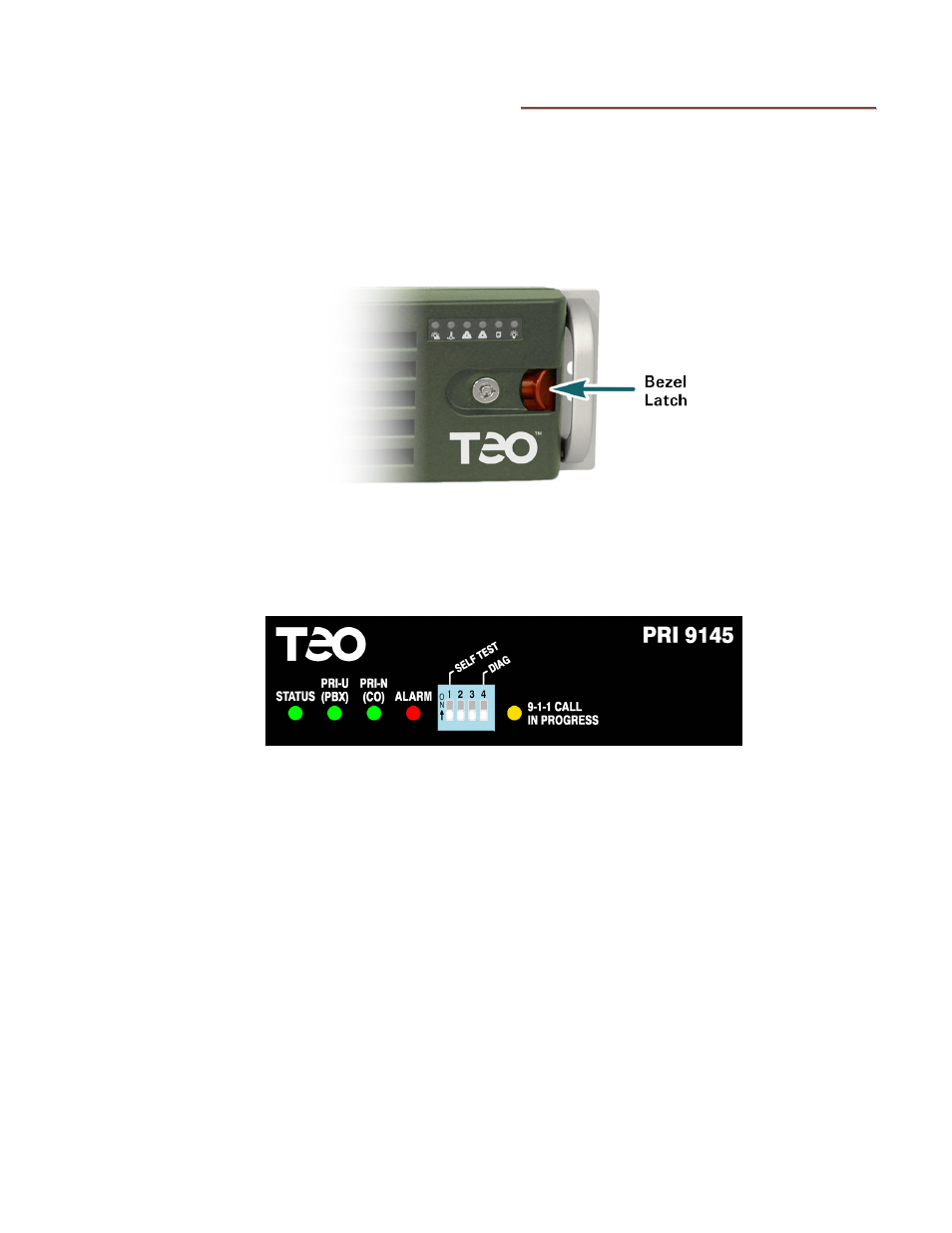
The E911 Response Server has two switch and indicator areas on the front panel.
F
F
r
r
o
o
n
n
t
t
B
B
e
e
z
z
e
e
l
l
R
R
e
e
m
m
o
o
v
v
a
a
l
l
Press the red lever left to unlatch the front bezel, and then pull the bezel forward to
remove. The bezel may be locked (using the included key) to prevent removal.
L
L
i
i
n
n
e
e
S
S
t
t
a
a
t
t
u
u
s
s
C
C
o
o
n
n
t
t
r
r
o
o
l
l
P
P
a
a
n
n
e
e
l
l
This control panel has indicators for line and internal processor functions, and a self test
switch.
STATUS – indicates that the processor and software are functioning correctly.
PRI-U (PBX) – shows the communication status of the ISDN PRI-U → PBX port.
PRI-N (CO) – shows the communication status of the ISDN PRI-N → Central Office port.
ALARM – indicates an alarm condition.
911 CALL IN PROGRESS – indicates 911 call activity.
SELF TEST Switch – initiates a test of the E911 Response Server (page 69).
Switches 2 – 4 are reserved for factory use only; they should be left in the OFF (down)
position.