2 − names and functions of parts, Top panel – Teac US-322 User Manual
Page 7
TASCAM US-322/366
7
2 − Names and Functions of Parts
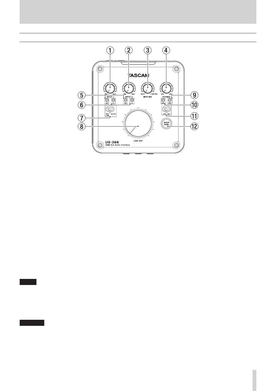
Top panel
1
INPUT 1 knob
Adjusts the input level from the INPUT 1/L MIC connector or
LINE/GUITAR jack.
Turn all the way left to minimize the level and all the way
right to maximize it.
Set so that the OL (overload) indicator does not light.
2
INPUT 2 knob
Adjusts the input level from the INPUT 2/R MIC connector
or LINE jack.
Turn all the way left to minimize the level and all the way
right to maximize it.
Set so that the OL (overload) indicator does not light.
3
MON MIX knob
If the MODE switch on the bottom of the unit is set to
MULTITRACK, adjusts the balance between the mix of
signals input through this unit's input connectors and the
signal mix output from the computer.
Turn all the way left toward INPUT to maximize the mix
of signals input through this unit's input connectors (and
minimize the signal mix output from the computer over
USB). Turn all the way right toward COMPUTER to maximize
the signal mix output from the computer (and minimize the
mix of signals input through this unit's input connectors).
NOTE
When the MODE switch on the bottom of the unit is set to
STEREO MIX, the MON MIX knob is disabled (the MON MIX
on the mixer panel screen will not move left or right even if
this knob is moved).
4
PHONES knob
Adjusts the PHONES jack output level.
CAUTION
Turn the PHONES knob to the minimum volume before
connecting headphones. Failure to do so could cause sudden
loud noises and damage hearing, for example.
5
SIG indicators
The SIG indicators light green when a signal (of at least –30
dBFS) is input to the corresponding INPUT 1/L or INPUT 2/R
channel.
The INPUT 1/L indicator is below the INPUT 1 knob, and the
INPUT 2/R indicator is below the INPUT 2 knob.
6
OL indicators
The OL indicators light red when a signal that is about to
distort (–2 dBFS or higher) is input to the corresponding
INPUT 1/L or INPUT 2/R channel.
The INPUT 1/L indicator is below the INPUT 1 knob, and the
INPUT 2/R indicator is below the INPUT 2 knob.
7
MIC/LINE-GUITAR switch
Set this according to what is connected to the INPUT 1/L
LINE/GUITAR jack.
Set this to GUITAR when connecting an electric guitar,
electric bass or other instrument with high output
impedance.
Set this to MIC/LINE when connecting an electronic
instrument, audio equipment, microphone or other device.
8
LINE OUT knob
Adjusts the output level of the line output jacks (OUT 1/L
and OUT 2/R).
9
USB indicator
This lights blue when the USB connection is normal.
0
48V indicator
This indicator lights red when the switch just below it is set
to 48V (phantom power on).