Sundance SMT916 User Manual
Page 11
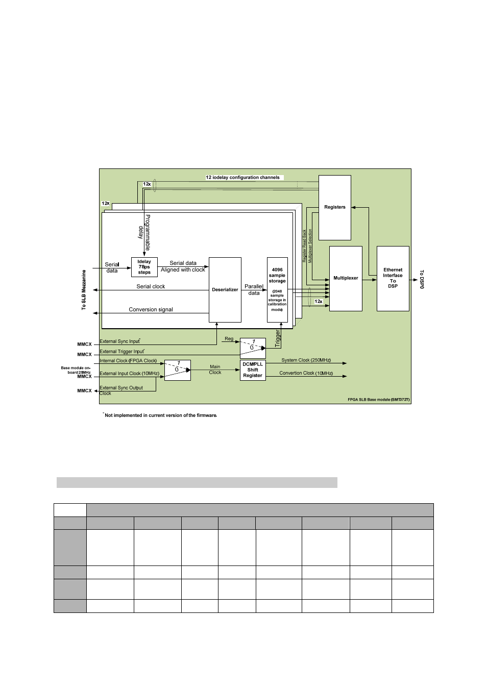
idelays. An initialisation routine will be run at start-up in order to work out the
delay required. Serial data is then turned into a 16-bit word. The data flow is routed
to a storage unit, which when enabled, allows data in. The storage units are enabled
via a trigger signal that could be coming from a register or a connector (external
trigger input – MMCX). Data capture into storage unit happens simultaneously for all
12 channels. The DSP is responsible for collecting data, one channel at a time. The
mux selects the current channel. Samples are transferred to the DSP via an Ethernet
interface. By default Storage unit are set to 4k samples (only 2k when
calibrating/aligning data line with clock – as an extra 2 bits are attached to the 16-
bit sample words).
Figure 4 - Firmware Block Diagram.
Registers implemented in the register block are described in the following parts of
this document.
3.4.2 Global Control Register – 0x4
Global control Register – 0x4 (Write-only register).
Byte
Bit 7
Bit 6
Bit 5
Bit 4
Bit 3
Bit 2
Bit 1
Bit 0
1
Clock
Source
Selection
External
Clock PLL
reset
External
Clock
Output
Enable
Reserved ADC11
Enable
ADC10
Enable
ADC9
Enable
ADC8
Enable
Default
‘0’ ‘0’
‘0’
‘0’
‘0’ ‘0’ ‘0’
‘0’
0
ADC7
Enable
ADC6
Enable
ADC5
Enable
ADC4
Enable
ADC3
Enable
ADC2
Enable
ADC1
Enable
ADC0
Enable
Default
‘0’ ‘0’
‘0’
‘0’
‘0’ ‘0’ ‘0’
‘0’