4 jtag cabling, Jtag cabling – Sundance SMT310 v.1.6 User Manual
Page 48
Page 48 of 50
SMT310 User Manual V1.6
When the buffered ComPort is reset to input, pins 1 and 23 are always driven and
pins 3 and 25 are always receivers. When the buffered ComPort is reset to output,
pins 3 and 25 are always driven and pins 1 and 23 are always receivers.
18.4 JTAG cabling
Two cable options exist for the SMT310; SMT501-JTAG is designed to connect two
SMTxxx carrier boards ie, SMT310 controlling an SMT328 VME carrier. The length of
SMT501 is 1 meter. A variation of the SMT501-JTAG is the SMT510-XDS. This
provides an XDS-510 14-way connector and will interface to a range of non-
Sundance products.
The 20-way JTAG connectors require the following cabling components:
Cable plugs
3M Scotchflex 10120-6000EL, FES part 038739R
Plug shells
3M Scotchflex 10320-A200-00, FES part 038759A
Cable type
3M Scotchflex KUCKMPVVSB28-10PAIR, FES part 038780G
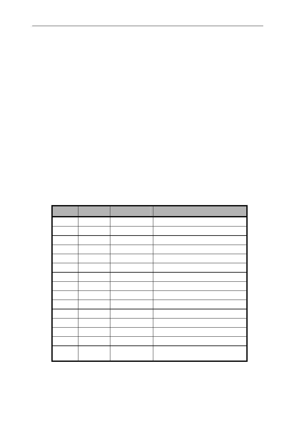
When using the SMT310s Buffered JTAG connector to connect to a JTAG slave, the
buffered connector pins are used as follows:
Pin
Signal
Direction
Description
1
TDI
OUT
JTAG data out
2 GND
3
TDO
IN
JTAG data in
4 GND
5
TMS
OUT
JTAG Test mode select
6 GND
7
TCK
OUT
JTAG clock 10MHz
8 GND
9
TCK_RET
IN
JTAG clock return
10 GND
11 /TRST
OUT
JTAG
Reset
12 GND
13 /RESET
OUT
Board
Reset
out
14
PD
IN
Presence detect when pulled high
15
/DETECT
OUT
Detect external JTAG controller when
grounded