Table 21 : buffered comport connector pin out – Sundance SMT310 v.1.6 User Manual
Page 47
Page 47 of 50
SMT310 User Manual V1.6
This cable has 13 individual pairs, with an overall shield, and an outer diameter of
7mm. Cable length should be as short as possible. The maximum tested cable length
is 1 meter.
On reset, each ComPort initialises to being either an input or an output.
Do not connect ‘Reset to Input’ ComPorts together.
Do not connect ‘Reset to Output’ ComPorts together.
However if this should occur, no damage will result, because ComPort direction
signals disable relevant ComPorts.
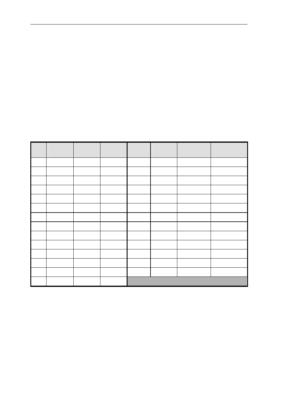
The following table shows connector pin-out and cable pair connections. This is
important, as the critical signals must be paired with a ground as shown. The
allocation to twisted pairs is based on grouping the data signals because they change
at the same time, so that crosstalk is not an issue. Each control signal has its own
ground:
Pin
Twisted
Pair
RTI
Signal
RTO
Signal
Pin
Twisted
Pair
RTI Signal
RTO Signal
1 1
I/O_OUT
I/O_IN
15 8
D2
D2
2 1 GND
GND 16 8
D3
D3
3 2 I/O_IN
I/O_OUT
17 9
D4
D4
4 2 GND
GND 18 9
D5
D5
5 3
/CSTRB
/CSTRB
19 10
D6
D6
6 3 GND
GND 20 10
D7
D7
7 4 /CRDY
/CRDY
21 11 VCC
VCC
8 4 GND
GND 22 11 GND
GND
9 5 /CREQ
/CREQ
23 12
/RST_OUT
/RST_IN
10 5 GND GND 24 12 GND
GND
11 6 /CACK
/CACK
25 13 /RST_IN
/RST_OUT
12 6 GND GND 26 13 GND
GND
13 7
D0 D0
SHELL - SHIELD SHIELD
14 7
D1 D1
Table 21 : Buffered ComPort connector pin out
The overall shield is attached to the body of the metal plug shell.
The signal VCC is fused on the board at 1 amp; it automatically resets when the load
is removed.