1 buffered comport, Buffered comport, Table 6 : comport configuration register – Sundance SMT310 v.1.6 User Manual
Page 17: Table 7 : comport selection
Page 17 of 50
SMT310 User Manual V1.6
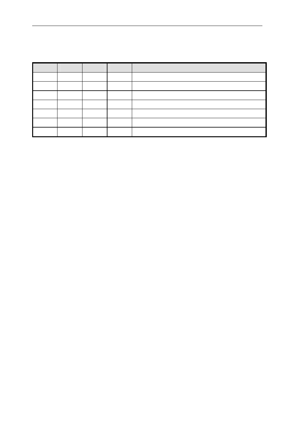
Table 6 : ComPort configuration register
The table below illustrates the different setting of the register.
CENc
CENb
SEL1
SEL0
Function
1
X
X
X
Connects DSP ComPort 3 to PCI Host
1
0
X
X
X
Disconnects DSP ComPort 3 to PCI Host
X
0
X
X
Disables all DSP connections to Buffered ComPort
X
1
0
0
Connect DSP ComPort 0 to Buffered ComPort
2
X
1
0
1
Connect DSP ComPort 2 to Buffered ComPort
2
X
1
1
0
Connect DSP ComPort 3 to Buffered ComPort
2 3
X
1
1
1
Connect DSP ComPort 5 to Buffered ComPort
2
Table 7 : Comport selection
1
SELC is a read-only bit that indicates, when 0, the detection of an FMS cable at J2. If SELC is
0 then CENc is overridden, since PCI Host is now connected to the external FMS connector J2.
2
SELB is a read-only bit that indicates, when 0, the detection of an FMS cable at J1. If SELB is
0 then CENb is overridden, since buffered ComPort is now connected to external FMS
connector J1.
The state of SEL1 also determines the direction (at reset) of the buffered ComPort,
because ComPorts 0 and 2 are defined (at reset) as outputs, and likewise 3 and 5 (at
reset) as inputs.
Important note for firmware v4.8 onwards:
An additional feature is supported from firmware v4.8, March 2007: Fitting jumper
JP9 links TIM site ComPort 3 directly to J2.
Specifically, JP9 forces Quick Switch C on and at the same time disables the PCI
Host ComPort CPLD. This connects TIM site ComPort 3 directly to the FMS
connector J2, and disconnects any link to the PCI Host. This setting overrides the
usual functions of CENc, and SELC but has no effect on CENb or CELB.
3
Care must be taken when JP9 is fitted, not to connect ComPort3 to the
Buffered ComPort also, or contention will occur.
8.1 Buffered
ComPort
From the TIM site, 4 ComPorts are taken to a back panel mounted connector via
quick switches. All signals are pulled up to +3.3 volts with 330 ohm resistors. The
active devices are mounted as close as possible to the connector they serve.
The back panel mounted connector is a 26 pin 3M type, (3M part number 10226-
5212JL). The connector pin-out is given in the following table, with pair numbers for
13 off twisted pair cable (3M part number KUCKMPVVSB28-13PAIR).
The buffer circuit for the connector is designed such that the reset direction is defined
by the TIM ComPort number to which it is connected. The quick switch arrangement