Sundance PARS User Manual
Page 41
Revision 11-wip-7
Page 41 of 70
Sundance Digital Signal Processing, Inc.
4790 Caughlin Parkway 233, Reno, NV 89519-0907, U.S.A.
email:
Tel: +1 (775) 827-3103
www.sundancedsp.com
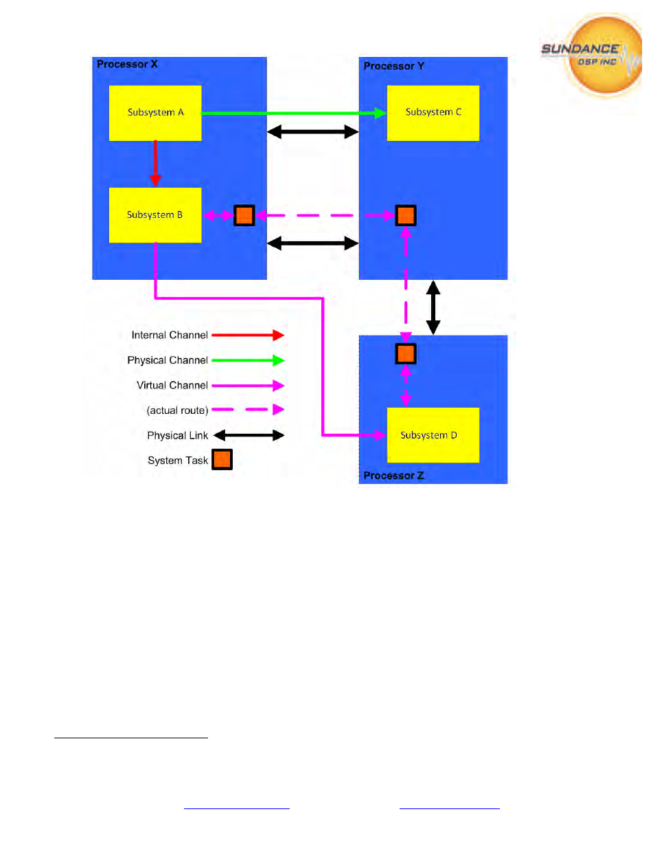
Figure 43 - How routing is implemented between processors
9
Figure 43, above, details three ways that subsystems communicate. Subsystem A and B communicate
via internal (fast) links on the same processor. Subsystem A and C communicate by using one of the
physical ‘wires’ between Processor X and Y. Subsystem B and D communicate using the ‘virtual
channel’ connection feature. PARS ensures that when the application is generated, the code necessary
to support this connection is loaded on to all the processors participating in establishing the connection;
in this case Processors X, Y and Z.
Unfortunately, this ‘virtual’ connection does not (currently) translate to the FPGA. Connections
between DSP and FPGA subsystems must be made with respect to the number and type of physical
links declared in the hardware system topology only. So for FPGA partitioning, the architect is advised
to group as much functionality onto the same FPGA as possible to minimize the number of connections
into and out of the FPGA-type processor.
9
Courtesy of 3L/Diamond v3.1.10 User Guide, pg. 33