Sundance PARS User Manual
Page 40
Revision 11-wip-7
Page 40 of 70
Sundance Digital Signal Processing, Inc.
4790 Caughlin Parkway 233, Reno, NV 89519-0907, U.S.A.
email:
Tel: +1 (775) 827-3103
www.sundancedsp.com
The hardware topology file names both the processor and the wires connecting them.
These names may be referenced in the model to ensure that the connections between the
subsystems are established over the desired wires
7
.
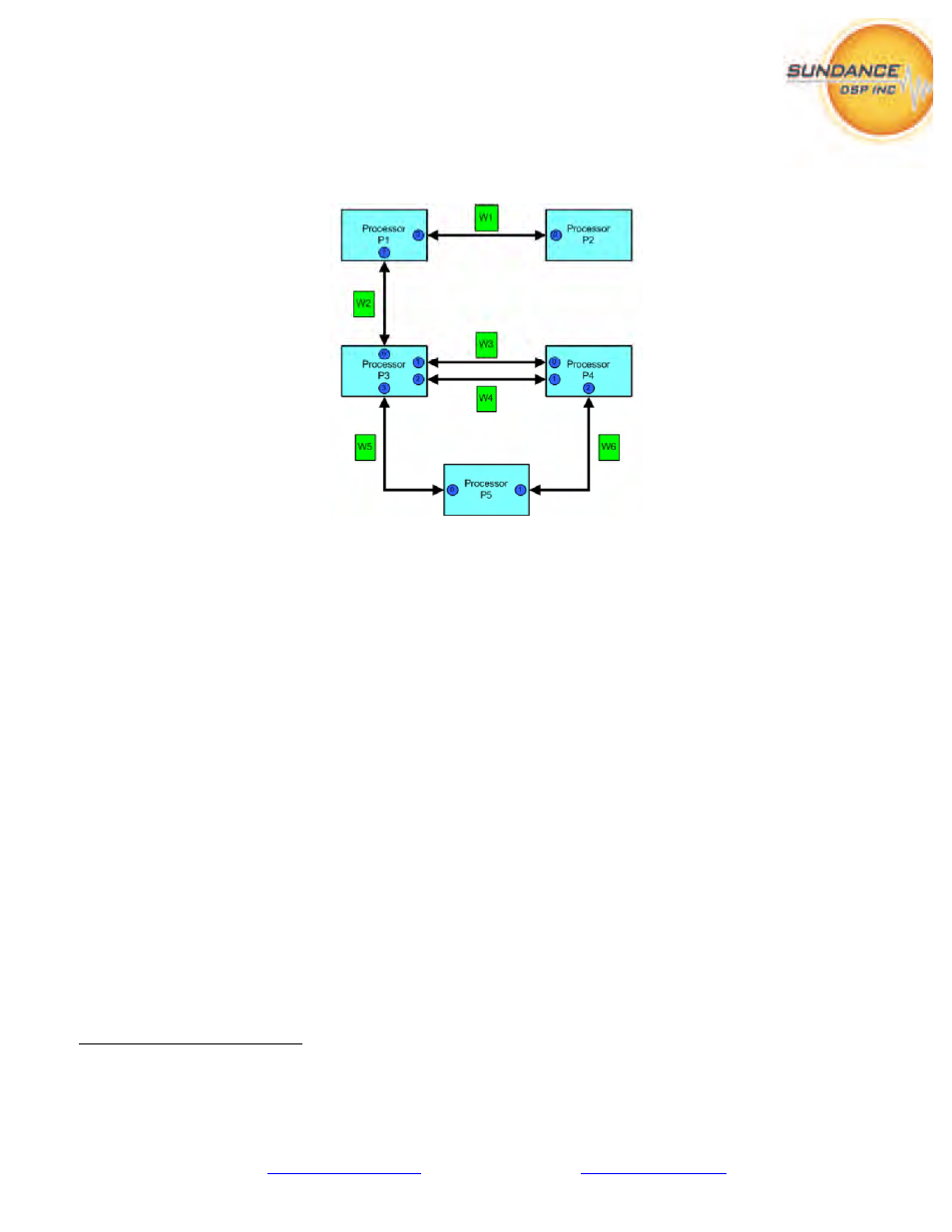
Figure 42 - Processors and wires in a hardware system
8
In the diagram, processor P2 has one link, processors P1 and P5 have two links, P4 has three links and
P3 has 4 links. The number of declared links has bearing on the flexibility afforded to the architect
when assigning subsystems to processors.
PARS ensures that all the necessary software/firmware on every processor is included in the generated
application to implement the communications that are defined by the connections described. Although
there are currently two ‘types’ of processor: DSP and FPGA, they are treated the same with respect to
declarations of wires connecting them.
Between DSPs, a special type of link termed ‘virtual’ is possible. Connections between any DSP
subsystems can be established to any other DSP subsystem. This has the effect of minimizing the need
to consider the physical system when describing a model.
7
This suggests that a naming convention be followed to allow models to reference different topologies easily
8
Courtesy of 3L/Diamond v3.1.10 User Guide, pg. 27