Install thermostatic mixing valve, Mount frame to wall – Sloan ELC-81000 Installaton User Manual
Page 4
4
Triple Station
1
2
3
3
2
1
16-1/2”
(419 mm)
3”
(76 mm)
INSTALLATION PROP
(ALL MODELS)
6-3/4”
(171 mm)
FINISHED FLOOR
D
(See VARIABLE
MOUNTING
HEIGHT CHART
On Page 3)
BACK SUPPORT
BRACE
SUPPORT ARM
CENTER SUPPORT
BRACKET
SIDE SUPPORT
BRACKET
1
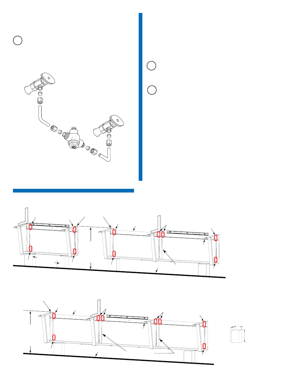
Install Thermostatic Mixing Valve
A
If necessary, install Mixing Valve between hot and cold water
supply.
2
Mount Frame to Wall
Double Station
1
2
3
3
3
3
1
1
1
Single Station
FINISHED FLOOR
D
(See VARIABLE
MOUNTING
HEIGHT CHART
On Page 2)
A
If desired, use the Installation Prop to raise the Frame to the
required height.
B
Mount Frame to wall using fasteners and washers that hold
over 200 lbf (pounds force) withdrawal load in the
following locations:
1. Top and bottom mounting holes at the extreme outer corners
of the Back Support Brace
2. Top and bottom mounting holes at both sides and closest to
each Central Support Bracket
3. The lower mounting hole in each Side Support Bracket
Fasteners may be optionally applied to any of the remaining
mounting hole locations.
If desired, apply adhesive to back surfaces of Frame.
Level Frame in ALL directions before tightening fasteners
securely.
Note: Stainless Steel Enclosure not shown on Frame to clarify fastener
locations.
Note: Protective gloves recommended when handling stainless steel.
BACK SUPPORT
BRACE
SUPPORT ARM
CENTER SUPPORT
BRACKET
SIDE SUPPORT
BRACKET
INSTALLATION
PROP