Prior to installation, Lavatory system rough-in (continued) – Sloan ELC-81000 Installaton User Manual
Page 3
3
PRIOR TO INSTALLATION
Prior to installing the Sloan Optima ELC-81000/82000/83000 Series
Lavatory System, install the items listed below. Also, refer to the
appropriate rough-in diagram on Page 2 or 3.
• Install electrical receptacle(s) for plug-in transformer(s) when
required — 120 VAC, 2 amp service for each ETF-233 (24 VAC, 35
VA) plug-in transformer used.
• Hot and cold water supply lines or tempered water supply line (If there
is no tempered water supply, install thermostatic mixing valve
between hot and cold water supply)
• Drain line(s)
Important:
• ADEQUATE STRUCTURAL SUPPORT IN OR BEHIND THE WALL IS
REQUIRED. REFER TO THE APPROPRIATE ROUGH-IN DIAGRAM ON
PAGE 2 OR 3 FOR DRY WEIGHT OF SINK.
STRUCTURAL SUPPORT
MUST HOLD OVER 200 LBF (POUNDS FORCE) WITHDRAWAL
LOAD FOR EACH FASTENER.
• INSTALL ALL ELECTRICAL WIRING IN ACCORDANCE WITH
NATIONAL/LOCAL CODES AND REGULATIONS.
• INSTALL ALL PLUMBING IN ACCORDANCE WITH APPLICABLE CODES
AND REGULATIONS.
• A 24 VAC STEP-DOWN TRANSFORMER MUST BE USED FOR
HARDWIRE APPLICATIONS.
• USE APPROPRIATE PRECAUTIONS WHILE CONNECTING
TRANSFORMER TO 120 VAC POWER SOURCE.
• DO NOT PLUG TRANSFORMER INTO POWER SOURCE (RECEPTACLE)
UNTIL ALL WIRING IS COMPLETED. PERMANENT DAMAGE TO THE
TRANSFORMER AND CIRCUIT CONTROL MODULE WILL RESULT IF
24 VAC WIRES TOUCH EACH OTHER OR SHORT WHEN POWER
SUPPLY IS ACTIVE.
• BEFORE CONNECTING FLEX HOSES TO SUPPLY STOPS, FLUSH ALL
WATER LINES UNTIL WATER IS CLEAR.
TOOLS REQUIRED FOR INSTALLATION
• Electric drill for drilling anchor holes.
• Standard sockets, basin wrench, and open end wrench set for
installing anchoring fasteners and faucets.
• Pipe wrench for installing drain lines.
• Phillips and straight blade screwdrivers.
• Tubing cutter
• Level
• Carpenter’s square
• Caulk gun
SINK LOCATION
Determine the appropriate wall location for the Lavatory System.
Consider that hot and cold water supply lines, drain line(s), and an
electrical source (receptacle or wiring depending on type of transformer
used) will be required. Compare the physical dimensions of the Lavatory
System to the space available for the installation. If wall is not load
bearing, a carrier may be required behind the wall. Refer to the
appropriate Rough-in diagram on Page 2 or 3 for Lavatory System
dimensions.
Prior to Lavatory System installation, electric wiring, water supply and
drain must be installed.
FACE
OF
WALL
18”
(457 mm)
15”
(381 mm)
15”
(381 mm)
30”
(762 mm)
B
(SEE CHART)
3-25/32”
(96 mm)
20-7/16”
(519 mm)
90”
(2286 mm)
15”
(381 mm)
15”
(381 mm)
30”
(762 mm)
15”
(381 mm)
15”
(381 mm)
30”
(762 mm)
CENTERLINE
CENTERLINE
CENTERLINE
FINISHED
FLOOR
CENTERLINE
CENTERLINE
CENTERLINE
17-7/16”
(443 mm)
3”
(76 mm)
110 VOLT, 60 Hz
15 AMP, GFCI
PROTECTED
ELECTRICAL
OUTLET (BY OTHERS)
9”
(229 mm)
8-1/2”
(216 mm)
A
(SEE CHART)
1-1/2” (38 mm)
DRAIN
(OPTIONAL)
4”
(102 mm)
1-1/2” (38 mm)
DRAIN (OPTIONAL)
4”
(102 mm)
C
(SEE CHART)
4”
(102 mm)
1/2” HOT/COLD SUPPLY LINES
3”
(76 mm)
1-1/2” (38 mm)
DRAIN
OPTIONAL PROTECTED
ELECTRICAL OUTLET,
DEPENDENT ON
SELECTED FAUCET
MODEL
9”
(229 mm)
9”
(229 mm)
110 VOLT, 60 Hz
15 AMP, GFCI
PROTECTED
ELECTRICAL
OUTLET (BY OTHERS)
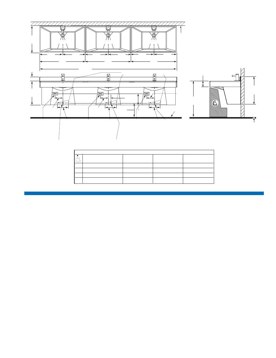
MODEL ELC-83000
Triple Station Lavatory System
Lavatory System Weight (Packaged):
Approximately 213 Lbs/97 Kg
LAVATORY SYSTEM ROUGH-IN (Continued)
VARIABLE MOUNTING HEIGHT CHART — Single, Double & Triple Station
DIMENSION
T.A.S.
T.A.S.
A.D.A.
DESCRIPTION
AGES 4-10
AGES 11-15
STANDARD
A
ROUGH-IN
18” (457 mm)
20” (508 mm)
22” (559 mm)
B
RECOMMENDED RIM HEIGHT 29-15/16” (760 mm) 31-15/16” (811 mm) 33-15/16” (862 mm)
C
FLOOR CLEARANCE MAX
12-1/2” (318 mm)
14-1/2” (368 mm)
16-1/2” (419 mm)
D
NOMINAL FRAME HEIGHT ‡
28-17/32” (725 mm) 30-17/32” (775 mm) 32-17/32” (826 mm)
‡
Refer to Step 2.