Install solenoid valve, Install transformer – Sloan ETF-80 Faucet User Manual
Page 4
2
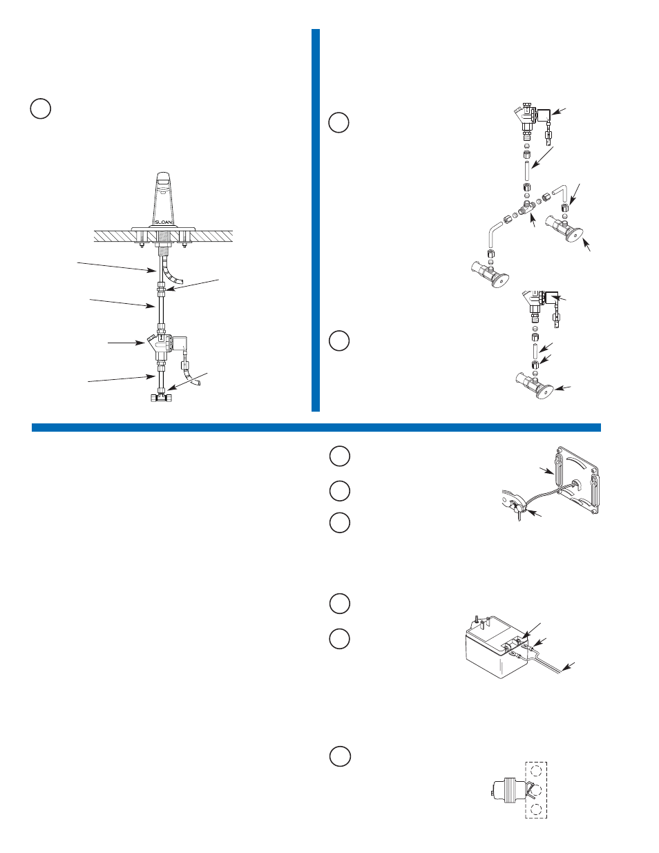
Install Solenoid Valve
A
Note: Flow direction of Solenoid Valve is indicated by an arrow on the
Valve Body.
Install the 1/4 inch end of the 1/4 to 3/8 inch Compression Fitting
onto the Spout’s copper Supply Tube. Connect 3/8 inch O.D.
Supply Tube between Compression Connection on Solenoid Valve
and Compression Fitting on Spout’s copper Supply Tube.
4
Install Transformer
Multiple Faucets
Multiple faucets can be powered by a single transformer that has been
properly sized. Allow a minimum of 15 VA of current rating for each
solenoid valve used. Refer to the following example to determine the
required current rating for 3 OPTIMA faucets.
Example:
Total number of OPTIMA faucets:
3
Total number of solenoid valves:
3
Multiply by current rating:
15 VA
——
Minimum current rating of required transformer: 45 VA
Transformers Available with the ETF-80 and ETF-880 Faucets
Standard Plug-In †
ETF-233
120 VAC
35 VA
Standard Box Mount
EL-248-40
120 VAC
40 VA
† In Canada, use ETF-416 (120 VAC, 35 VA).
Optional Transformers Available from Sloan
Box Mount
EL-154
120 VAC
50 VA
Foot Mount
EL-208
120 VAC
100 VA
Box Mount
EL-342
240 VAC
50 VA
All Sloan transformers are 50/60 Hz.
Other transformers (not supplied by Sloan) may be used provided they
meet UL requirements for Class 2 transformers.
PLUG-IN TRANSFORMERS
Important: DO NOT plug Transformer into receptacle until all wiring has
been completed. The Transformer is supplied with a 10 foot Cable;
however, this Cable can and should be shortened to meet installation
requirements.
A
Strip ends of Transformer Power Cable
approx. 3/16 to 1/4 inch (5 to 6 mm).
E
Install Crimp Connectors and
connect Power Cable ends to
Transformer Terminals.
D
Connect Power Cable to Terminal Block on Connector Board. See
Step 6.
C
Insert Power Cable and Strain Relief into
hole at back of Control Module. Install right angle Strain Relief so
that Power Cable enters the Control Module from the bottom.
B
Install Strain Relief 3 inches (76 mm)
from one end of Power Cable.
BOX MOUNT TRANSFORMER
Important: DO NOT supply power to primary side of Transformer until
wiring is completed.
Mount Transformer on a metal electrical junction box (supplied by others). (“J”
box should be mounted inside chase wall or above ceiling.) Install Transformer
within 50 feet (15.24 meters) of Faucet. 18 gauge wire is recommended.
A
Run wires from secondary side
of Transformer to 3/8 inch (10
mm) hole at back of Control
Module Enclosure. If necessary,
wires can be run through wall and
then inserted through hole in back of
Control Module Enclosure.
CONTROL
MODULE
BASE
POWER CABLE
STRAIN
RELIEF
CRIMP
CONNECTORS
TRANSFORMER TERMINALS
24 VAC
SECONDARY
120 VAC
PRIMARY
BOX MOUNT
TRANSFORMER
(EL-248-40
SHOWN)
3
Connect Supply Line(s) from
Supply Stop to Solenoid Valve Inlet
For Dual Line Hot and Cold Water
Supply Applications
Install a 3/8 inch (10 mm) copper supply
tube between Bak-Chek
®
Compression Tee
and hot and cold supply stops. (Supply
stops and copper supply tube furnished by
installer.) Install a 3/8 inch (10 mm) copper
supply tube between Bak-Chek
®
Compression Tee and inlet side of
Solenoid Valve. Tighten
Compression Fittings securely.
Note: Failure to install the Bak-Chek
®
Tee
can result in a cross flow connection
when the faucet is off and the supply
stops are open. If pressure of the hot
and cold water supply differ, hot water
can migrate into the cold water supply or
vice-versa. Most plumbing codes require that
the Bak-Chek
®
be used to prevent this.
3/8” (10 mm)
BAK-CHEK
®
TEE
USED ON DUAL
WATER SUPPLY
APPLICATIONS
ONLY
3/8” (10 mm)
COMPRESSION
FITTING
3/8” (10 mm)
SUPPLY TUBE
SOLENOID
VALVE
SUPPLY
STOP
A
3/8” (10 mm)
COMPRESSION
FITTING
3/8” (10 mm)
SUPPLY TUBE
SOLENOID
VALVE
SUPPLY
STOP
B
For Single Line Water Supply Applications
Install a 3/8 inch (10 mm) copper supply tube
between the supply stop and inlet side of
Solenoid Valve. (Supply stop and copper
supply tube furnished by installer.) Tighten
Compression Fittings securely.
Important: Keep thread sealant out of your waterway and prevent
component part damage! Do not use sealant on compression fittings.
When thread sealant is used, do not apply it to the first two “starter”
threads.
4
COPPER
SUPPLY
TUBE
3/8” SUPPLY
TUBE (NOT
SUPPLIED)
1/4 TO 3/8 INCH
COMPRESSION
FITTING
SOLENOID VALVE
3/8” (10 mm)
BAK-CHEK
®
COMPRESSION
TEE
3/8” SUPPLY
TUBE (NOT
SUPPLIED)
Important: Flush dirt, debris, and sediment from the supply line(s).
Important: Twist stranded ends of Power Cable before inserting into
Terminal Block. Fraying of Stranded Power Cable Wire can cause a short
and damage the Control Module and Transformer when powered.