Sloan 110 Dolphin Flushometer User Manual
Page 4
4
TAILPIECE
COUPLING
CONTROL
STOP
1
FLUSHOMETER
BODY
FLUSH
CONNECTION
COUPLING
2
O-RING
G-44
FRICTION
RING
SPUD
COUPLING
3
C/L
FIXTURE
C/L
SUPPLY
FLUSH
CONNECTION
ADJUSTABLE
TAILPIECE
A
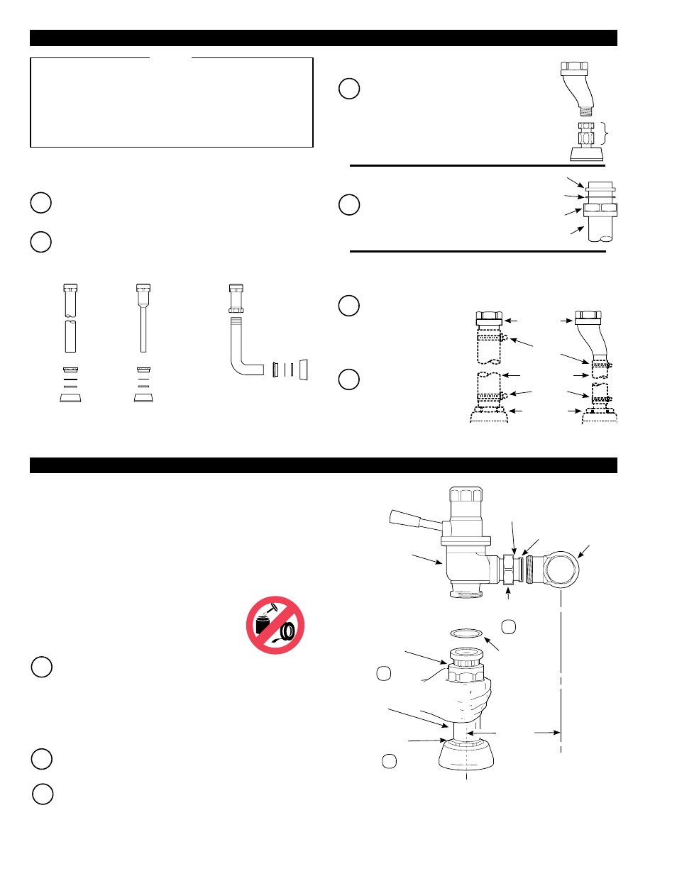
Slide the Spud Coupling (B), Nylon Slip Gasket (C), Rubber Gasket
(D), and Spud Flange (E) over the Vacuum Breaker Tube (A).
B
Insert Tube into Fixture Spud. Hand tighten the Spud Coupling (B)
onto Fixture Spud.
A
Position the 3/4” Spud Flange (H), then attach the
3/4” to 1/2” Reducer (G) to the 1/2” Spud and to
the 3/4” Flush Connection with 1/2” Offset (F).
3A — Install Vacuum Breaker Flush Connection
For all instal lations except Shipboard Shock Mount and Type II Class B
Rigid Installations.
MODELS 110/111, 115, &
SHIPBOARD TYPE I CLASS B MODEL 186
MODEL 120
A
A
B
C
D
E
B
E
D
C
A
B
C
D
E
G
F
H
3C — “-XYV” Variation Installations
For Models WITHOUT a Vacuum Breaker
3D — Class A Shock Mount Installations
For Class A Shock Mount Models ONLY — NOTE: Clamps, Rubber
Hose and Fixture Connections are NOT supplied by Sloan
3B — Shipboard Model Type II Class B Rigid Installations
A
Cut Flush Tube to proper
length at the site of
installation. Allow MIN.
length of 5” (127 mm)
between Tube ends when
using Rubber Hose.
B
Clamp Hose to scored
end of Flush Tube.
If Tube needs to be
shortened, do NOT cut
off all of the scoring.
A
Slide Coupling Nut, Slip Gasket, and
Gasket over Flush Tube. Slide Flush
Tube into Bottom of Flushometer Body.
Hand tighten Coupling Nut to secure.
GASKET
SLIP
GASKET
COUPLING
NUT
FLUSH TUBE
FLUSH TUBE
CLAMPS
RUBBER HOSE
FIXTURE
CONNECTION
CLAMPS
4-3/4”
(121 mm)
±1/2”
(13 mm) †
Vacuum Breakers are usually NOT required with non-potable
water supplies. When ordering a Flushometer without a Vacuum
Breaker, please specify the “-XYV” variation.
Depending on your application, refer to the appropriate Step(s)
in this section.
If a Class A Shock Mount is already installed, proceed to Step 4.
NOTE
C
Align Flushometer Body. Using a wrench, securely tighten
couplings in the order given: (1) Tailpiece Coupling, (2) Flush
Connection Coupling and (3) Spud Coupling.
B
Align Flushometer directly above the Flush Connection. Tighten
Coupling by hand.
NOTE: With the exception of Control Stop inlet, DO
NOT use pipe sealant or plumbing grease on any valve
component or coupling.
SLOAN ADJUSTABLE TAILPIECE — The Sloan Adjustable
tailpiece compensates for “off-center” roughing-in on the job. Maximum
adjustment of the Sloan Adjustable Tailpiece is ½” (13 mm) IN or OUT
from the standard 4¾” (121 mm) (c/l of Valve to c/l of Control Stop). If
roughing-in measurement exceeds 5¼” (133 mm), consult factory for
longer tailpiece.
SLOAN GROUND JOINT TAILPIECE — If a Ground Joint
tailpiece has been specified (recommended for saltwater and seawater
applications), there is no lateral adjustment. Therefore, the 4¾” (121
mm) rough-in must be EXACT.
A
SLOAN ADJUSTABLE TAILPIECE — Lubricate tailpiece
O-ring with water. Insert Adjustable Tailpiece into Control Stop.
Tighten Tailpiece Coupling by hand.
SLOAN GROUND JOINT TAILPIECE — Place end of Ground Joint
Tailpiece against Control Stop. Tighten Tailpiece Coupling by hand.
† This measurement can vary +/-1/2” (13 mm) only when an adjustable tailpiece
is used.
3 - INSTALL FLUSH CONNECTION
4 - INSTALL FLUSHOMETER