Sloan 110 Dolphin Flushometer User Manual
Page 3
X
3
A
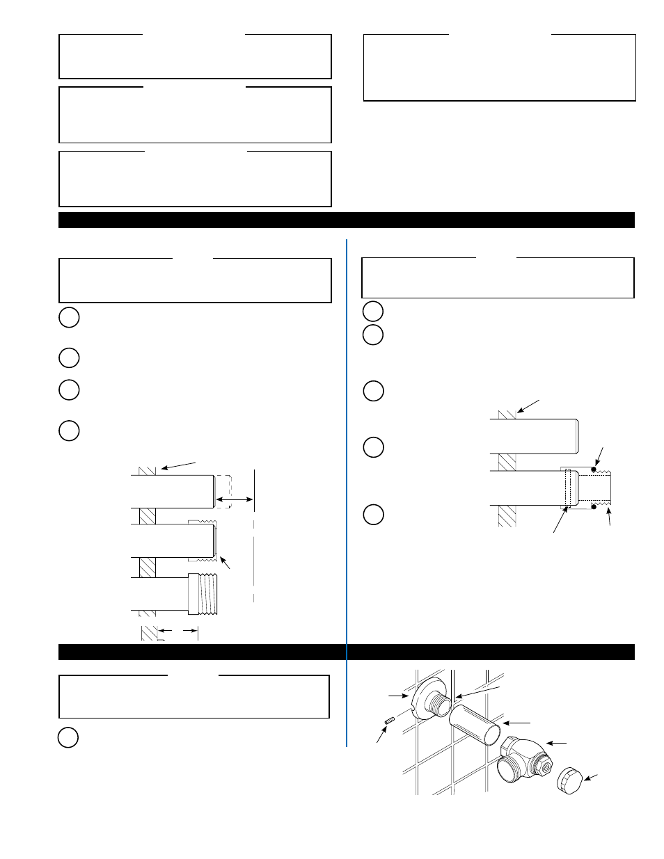
Measure from finished wall to C/L of Fixture Spud. Cut pipe 1¼”
(32 mm) shorter than this measurement. Chamfer O.D. and I.D. of
water supply pipe.
WATER SUPPLY PIPE
FINISHED WALL
1-1/4”
(32 mm)
C/L OF
FIXTURE
SPUD
SWEAT
SOLDER
ADAPTER
B
Slide Threaded Adapter fully onto pipe. Sweat solder the Adapter
to pipe.
BAK-CHEK
®
CONTROL STOP
COVER TUBE †
IRON PIPE NIPPLE OR
COPPER PIPE WITH
SWEAT SOLDER ADAPTER
SETSCREW †
SUPPLY
FLANGE
C
Measure from finished wall to first thread of Adapter or threaded
supply pipe (dimension “X”). Cut Cover Tube
to this length.
D
Slide Cover Tube over pipe. Slide Wall Flange over Cover Tube
until against wall. Secure the Wall Flange and Cover Tube with the
Setscrew. Tighten with a 1/16” hex wrench.
Install the Sloan Bak-Chek
®
Control Stop to the water supply pipe.
Tighten the Control Stop coupling with a wrench. Position the
outlet as required.
DO NOT install Vandal Resistant Stop Cap at
this time.
A
STOP CAP
A
Insert Silver Brazing Ring into Sil-Braze Inlet Adapter.
B
Place adapter over end of copper pipe. Diameter of copper pipe
varies depending upon your application:
Shipboard Type I Closet Valves: Pipe Diameter = 1” (25 mm)
Shipboard Type II Urinal Valves: Pipe Diameter = 1/2” (13 mm)
C
Solder adapter to copper
pipe. Allow pipe and
adapter to cool before
proceeding.
E
Make sure that the
Control Stop 1” (25 mm)
straight thread fits tight
against the o-ring.
D
Place o-ring over male
thread of the adapter.
Make sure that the o-ring
is seated against the
shoulder of the adapter.
WATER SUPPLY PIPE
O-RING
SIL-BRAZE
INLET
ADAPTER
SILVER BRAZING
ALLOY RING INSERT
FINISHED WALL
†COVER TUBE AND CAST SETSCREW
SUPPLY FLANGE ARE AVAILABLE IN
“YBYC” SWEAT SOLDER KIT.
Install Sweat Solder Adapter ONLY if supply pipe does not
have a male thread. If your installation includes a supply
line with a threaded iron pipe nipple, proceed to Step 2.
NOTE
If you are NOT installing the Sil-Braze Inlet Adapter that
can be furnished with a Shipboard flushometer, proceed to
Step 2.
NOTE
Stops furnished with a Sil-Braze Inlet Adapter have a straight
thread with an O-ring seal. Do NOT use pipe thread sealant on
this connection.
NOTE
With the exception of Control Stop Inlet, DO NOT use pipe
sealant or plumbing grease on any valve component or
coupling!
!!! IMPORTANT !!!
Protect the chrome or special finish of Sloan Flushometers —
DO NOT USE toothed tools to install or service these valves.
Use a Sloan A-50 Super-Wrench™, Sloan A-109 Plier Wrench
or smooth jawed spud wrench to secure all couplings. Also
see “Care and Cleaning” section of this manual.
!!! IMPORTANT !!!
This product contains mechanical and/or electrical components
that are subject to normal wear. These components should
be checked on a regular basis and replaced as needed to
maintain the valve’s performance.
!!! IMPORTANT !!!
Please take the time to read this manual to ensure proper
product installation and longevity. Also, please visit our website to
download our most recent documentation for this product.
If you have questions about how to install your
Sloan flushometer, consult your local Sloan Representative
or call Sloan Technical Support at:
1-888-SLOAN-14 (1-888-756-2614)
Never open Control Stop to where the flow from the valve
exceeds the flow capability of the fixture. In the event of a
valve failure, the fixture must be able to accommodate a
continuous flow from the valve.
!!! IMPORTANT !!!
1 - INSTALL OPTIONAL ADAPTER
2 - INSTALL CONTROL STOP
Sweat Solder Adapter (DO NOT USE in Saltwater Applications)
Sil-Braze Inlet Adapter (For Shipboard Models Only)