Wiring, Modgas-xwr technical guide, Anode an od e an o d e – Orion System MODGAS-XWR User Manual
Page 9: C cable connecting to the appropriate i
MODGAS-XWR Technical Guide
WIRING
9
Fan Enable
Low Speed Fan
YS102530 REV 1
GAS
V
ALVE
2
GAS
V
AL
V
E
1
PO-IGN2
PO-IGN1
COMMON
RLY4
RLY3
RLY2
RLY1
WATTMASTER
CONTROLS
MADE IN USA
AUX BIN
HEAT EN
RESET IN
OPTIONS
SAT
GND
AUX AIN
GND
STATUS
ALARM
COMM
POWER
ANODE
AN
OD
E
AN
O
D
E
M
ENTER
UP
DOWN
ALARM
MENU
OE377-26-00060
MODGAS-XWR
AAON No.: V20780
WattMaster No:
#SW000055
Rev.: 1A
E-BUS
CONNECT
I2C
CONNECT
+24
V
AC
GND
CONTACT RATING
IS 1 AMP MAX
@ 24 VAC
HEAT 1
LOW SPEED
FAN
PROOF OF IGNITION 1
PROOF OF IGNITION 2
GAS VALVE 2
GAS VALVE 1
GAS
V
AL
VE
TERMINALS
HEAT 2
COMMON
RELAY OUTPUT
TERMINALS
INPUT TERMINALS (TYPE)
HEAT ENABLE (BI)
AUX. (BI)
GND
RESET INPUT (AI)
SAT INPUT (AI)
GND(AI)
GND
AUX. (AI)
www.aaon.com
MODGAS-XWR CONTROLLER
(OE377-26-00060)
Supply
Air Temperature
Sensor
Mount In Supply
Air Duct
Connect
to AI2 & GND
On Main Controller
Supply Air Temperature
Sensor
EBC E-BUS Cable
Connects To
VCB-X Controller’s
Expansion
Port
Modular Cable Connects To
VCM-X E-BUS Controller’s
Expansion Port
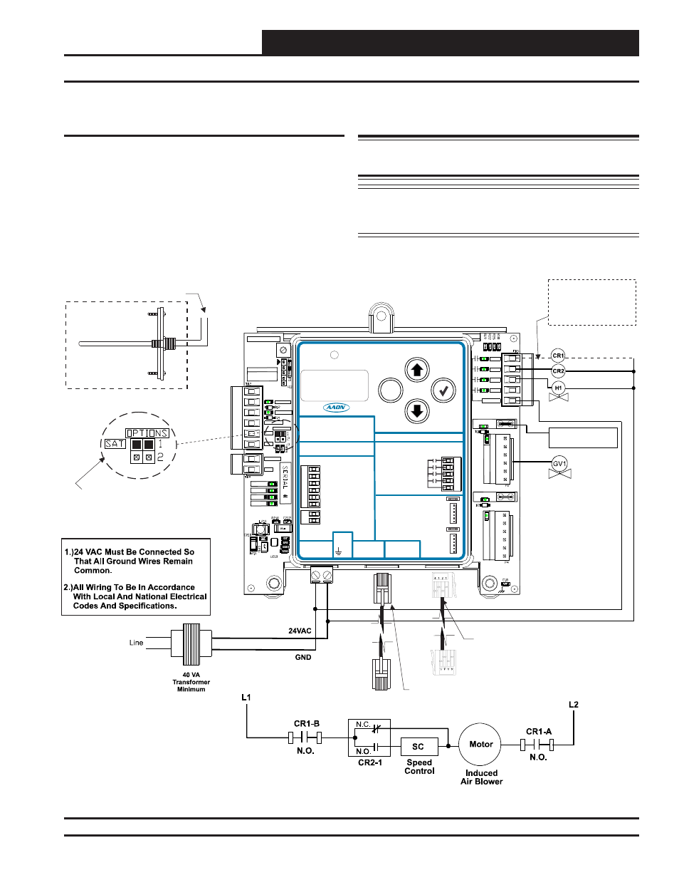
The SAT OPTIONS Jumper Setting
Should Be Set to 1.
See
For Settings.
Only One Supply Air Temperature Sensor
Can Be Used Per Application.
Table 9, Page 26
Modulating
Gas Valve 1
Proof of Ignition
Signal 1 (24 VAC)
Heat Valve 1
Check Your Fan
Relay Wiring (RLY1)
Schematic For
Proper Wiring.
Single Modulating Valve No Staging - Communicating Wiring
Figure 6: Single Modulating Valve No Staging Communicating Wiring Diagram
Single Modulating Valve No Staging -
Communicating Wiring
This confi guration operates as Stand-Alone (Figure 2, page 5) or
communicating with an AAON Unit Controller (Figure 6, below).
For connection to a VCB-X Controller or VCB-X Expansion Module,
use an E-BUS Cable connecting to the appropriate E-BUS ports on
those controllers.
For all other controllers, including VCM-X or Expansion Modules, use
an I
2
C Cable connecting to the appropriate I
2
C ports on those controllers.
WARNING: Do Not Connect Power To VOUT/Ground
Terminal
Block!
NOTE: If additional fi xed stages are required, these should be
confi gured and wired to the AAON Unit Controller’s
relays.