Lcd display screens, Alarm & setpoint screens, Modgas-xwr technical guide – Orion System MODGAS-XWR User Manual
Page 17: 17 alarm screens, Setpoint screens
MODGAS-XWR Technical Guide
LCD DISPLAY SCREENS
17
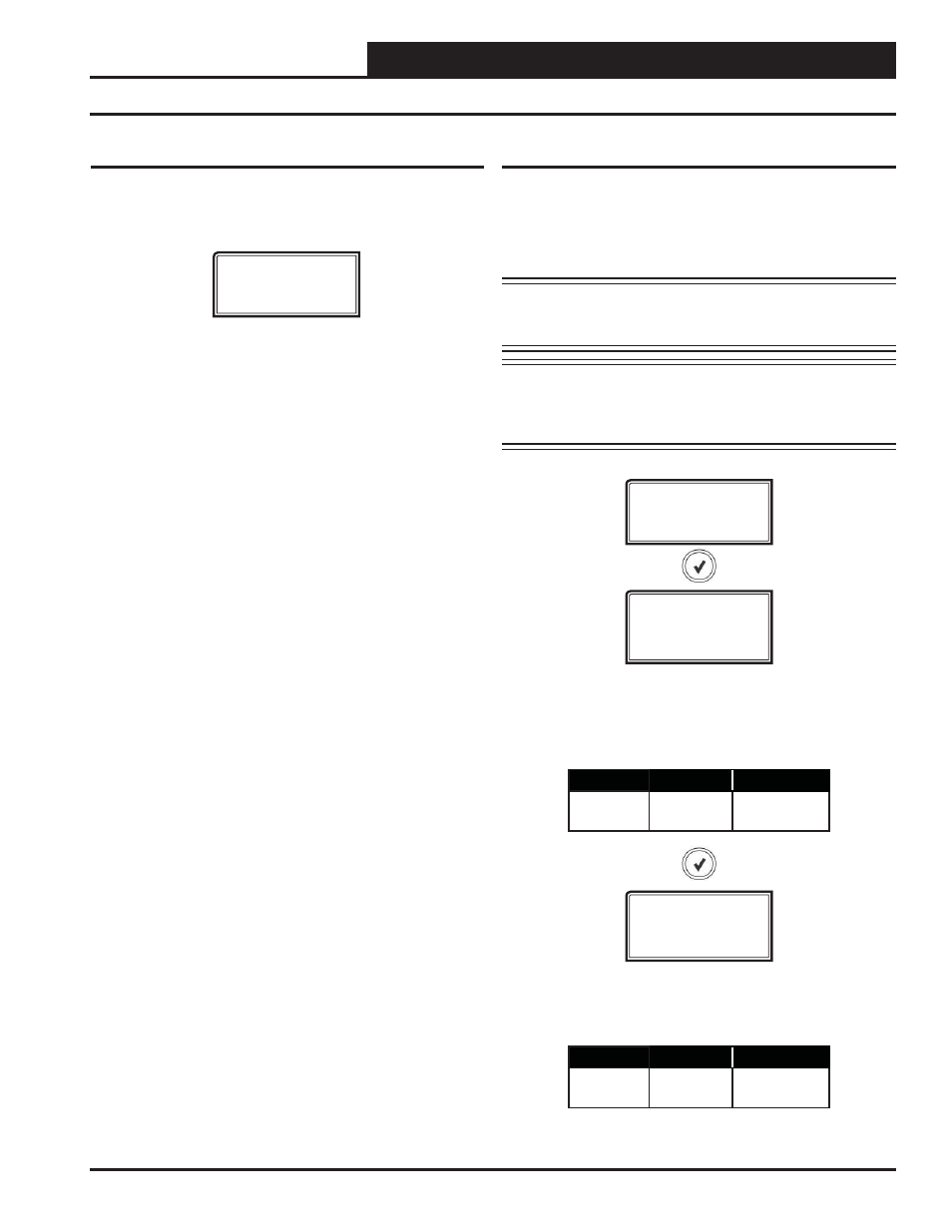
Alarm Screens
Refer to the following map when viewing Alarm Screens. These screens
will display automatically when alarms are present. For more informa-
tion, see pages 20-22.
ALARMS
ALARMS
The alarms are as follows:
NO ALARMS:
This will be shown if there are no current alarms.
V1 NOT DETECTED:
Gas Valve 1 is not detected.
V2 NOT DETECTED:
Gas Valve 2 is not detected.
V1 NO PROOF OF FLAME:
No Proof of Flame Ignition Module input
is detected..
V2 NO PROOF OF FLAME:
No Proof of Flame Ignition Module input
is detected.
SAT CUTOFF:
This indicates a Supply Air Temperature Cutoff Alarm
condition which is activated if the SAT has risen above 200ºF. The alarm
will go away if after a fi xed delay period the SAT has dropped below
200ºF.
SAT FAILURE:
The Supply Air Temperature sensor has been discon-
nected for more than 60 seconds. This alarm will be disabled when the
sensor is reconnected.
COMM T/O ERROR:
Communications have been lost with the main
controller. This alarm will disable when communications resume.
Alarm & Setpoint Screens
Setpoint Screens
Refer to the following map when navigating through the Set-
point Screens. From the SETPOINT Screen, press
to
scroll through the screens and change setpoints. Use the
and
arrow keys to change your selections. Then press
to save the new setpoint.
WARNING: The
key must be pressed after
changing setpoints for your entries to be saved
for subsequent power-ups.
NOTE: When the MODGAS-XWR is operating in Communi-
cations Mode, these setpoints screens will not appear
on the LCD display because they are controlled by the
Main Controller.
SETPOINT
SAT SP
40-150°F
4-65°C
RESET SP
40-150°F
4-65°C
HEATING SUPPLY AIR TEMPERATURE SETPOINT
This is the target temperature while the heating is enabled. If you are
using the reset signal, this is the setpoint it will calculate to at zero volts.
The Setpoint Screen will display only in stand-alone mode.
Minimum
Default
Maximum
40°F
4°C
120°F
49°C
150°F
65°C
RESET HEATING SUPPLY AIR SETPOINT
This is maximum temperature at which the Supply Air Temperature will
reset to. The Setpoint Screen will display only in stand-alone mode.
Minimum
Default
Maximum
40°F
4°C
120°F
49°C
150°F
65°C