Lcd display screens, Confi guration & diagnostic screens, Modgas-xwr technical guide – Orion System MODGAS-XWR User Manual
Page 19: Diagnostic screens
MODGAS-XWR Technical Guide
LCD DISPLAY SCREENS
19
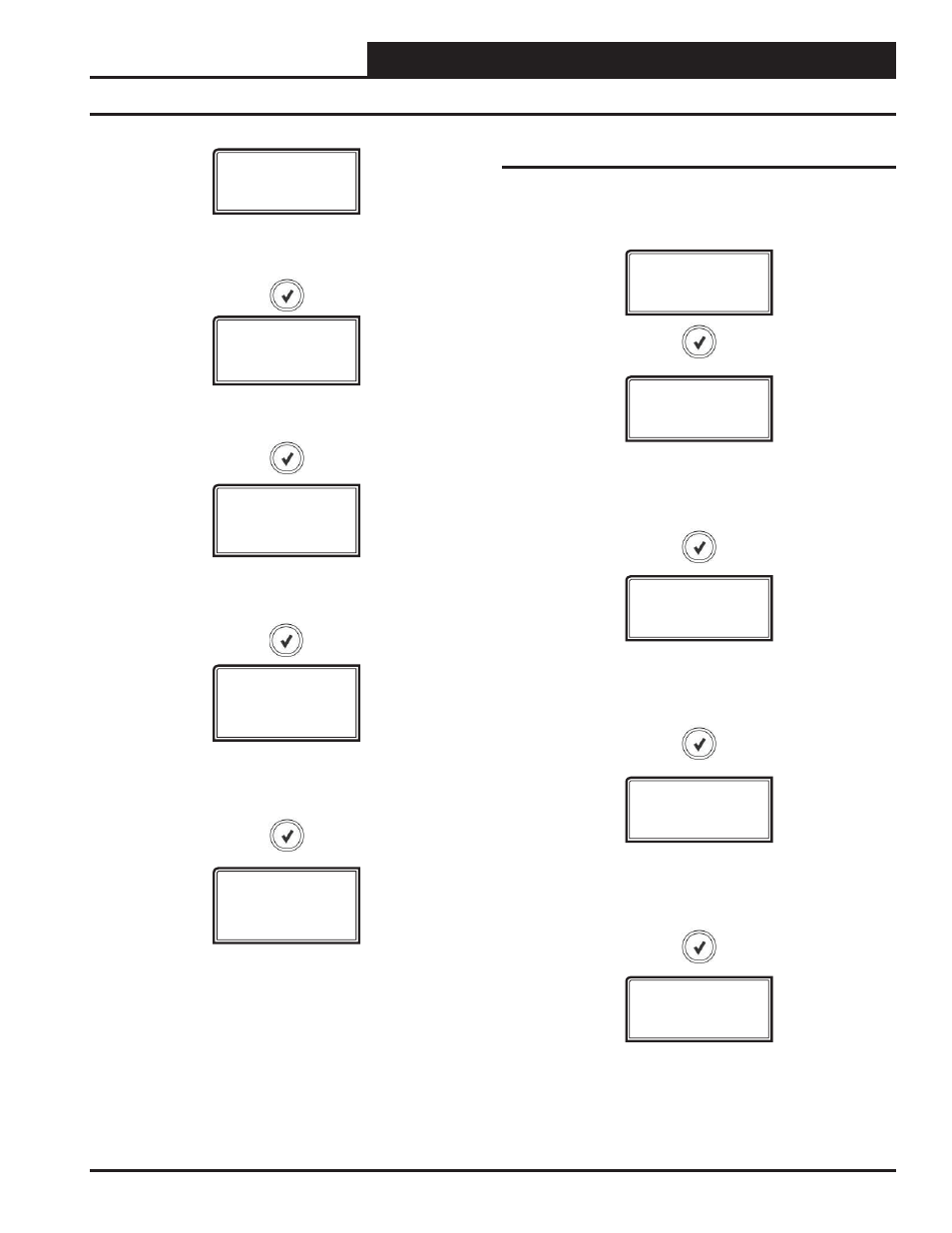
Confi guration & Diagnostic Screens
ADDRESS
1 TO 4
TMPSCALE
FAHRENHT
CURRENT ADDRESS OF THE BOARD
The address is only used in communicating mode. Default = 1
Diagnostic Screens
Refer to the following map when navigating through the Diagnostic
Screens. From the DIAGNSTC Screen, press
to scroll
through the screens.
DIAGNSTC
WDOG CNT
#
PWER CNT
#
WATCH DOG TIMER
Displays the number of times the board has been reset due to
watchdog timer overfl ow.
TEMPERATURE SCALE
Fahrenheit (default) or Celsius.
This setting is used only in stand-alone mode.
VLV1 ERR
#
VALVE 1 COMMUNICATION
Displays the number of received PWM communication error signals
from Valve 1. Not necessarily failed communications.
POWER LOSS COUNT
Displays the number of times the board has been reset
due to power loss.
VLV2 ERR
#
VALVE 2 COMMUNICATION
Displays the number of received PWM communication error signals
from Valve 2. Not necessarily failed communications.
STG UP
DLY
1 TO 10
STAGE UP DELAY
Range is 1 to 10 minutes. Default is 3.
STG DOWN
DLY
1 TO 10
STAGE DOWN DELAY
Range is 1 or 10 minutes. Default is 1.
S/A MODE
AUTO DETC or
LOCKED
STAND ALONE MODE
Auto-detect or Locked. Default is Auto-detect.