Communication devices, Vcm-x component & systems wiring 71 – Orion System VCM-X E-BUS Component User Manual
Page 71
VCM-X Component & Systems Wiring
71
Communication Devices
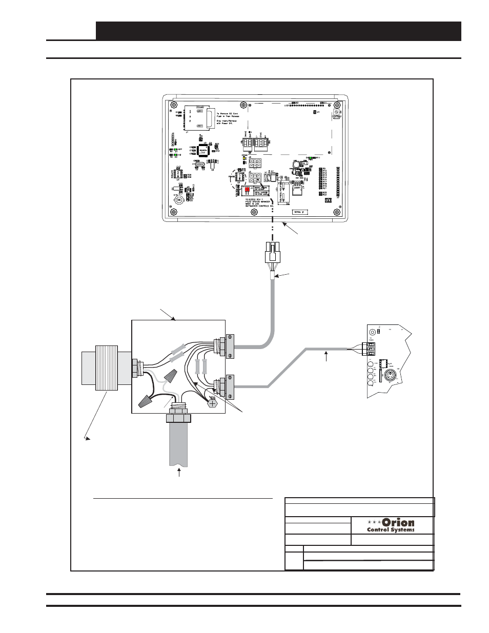
System Manager Wiring Details For Using The Pigtail
01/16/13
Notes:
1.) All wiring to be in accordance with local and national electrical codes
and specifications.
DATE:
DESCRIPTION:
PAGE
DRAWN BY:
Component Wiring Diagram
SysMgrPigtail1C.CDR
OE392-12 Modular System Manager
1 of 1
1.) All wiring to be in accordance with local and national electrical codes
and specifications.
2.) All modular power/comm cables are to be WattMaster part
number PCC-xx or PCCE-xx cables.
Notes:
B. Crews
Notes:
1.) All wiring to be in accordance with local and national electrical codes
and specifications.
WHITE
(T)
BLACK (R)
RED
(24
VA
C)
BROWN (GND)
GREEN
(GND)
Drain Wire (Shld)
LINE
VOLTAGE
LINE VOLTAGE
2-Conductor Shielded
18-Gauge
Communications Wire
FILENAME
JOB NAME
OE392-12 Modular System
Manager SD
Back of Front Cover
Handy Box, Conduit,
Fittings, Wire Nuts,
Butt Splices Etc.,
(By Others)
Controller Board
T
SHLD
R
HZ000121
Modular Pigtail Cable
Supplied With System Manager
Class 2 Transformer
Rated For 6 VA Minimum
(By Others)
05/18/15
DATE:
By: S. Olson
4
GB
System Manager Modular Cable Pigtail - Wiring Detail
Figure 49: OE392-12 Modular System Manager SD Cable Pigtail - Wiring Detail