Networked single loop system, Vcm-x component & systems wiring 28, Zone – Orion System VCM-X E-BUS Component User Manual
Page 28: Gn d ain 2 ain 1 +5v tb2, Cx 14 network driver rn3, Enter clear esc prev next down up, Minus, St a tus se tpoints schedules al arms overrides, Tb3 stat gnd 24vac r shld t tb2 rec
Zone
Zone
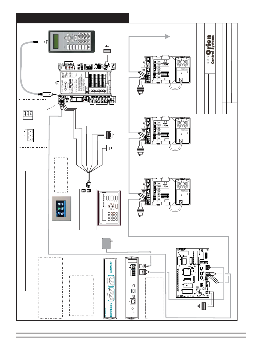
Networked Single Loop System
VCM-X Component & Systems Wiring
28
EPROM
U3
U5
RAM
CX2
1
U2
R1
C3
U4
CX3
CX4
YS101818P552
PROCESSORPBOARD
CX5
C1
U1
R2
CX1
CX6
WDOG
U6
PHILIPS
D1
P1
X1
C2
C4
0-10V
4-20mA
THERM
R27
R31
D4
GN
D
24VA
C
TB1
D5
C1
1
U12
LED 2
POWER
V1
R25
R26
C7
CX
15
CX13
PROC.
DRIVER
LOOP
DRIVER
LOCAL
L
OOP
GN
D
AIN
2
AIN
1
+5V
TB2
P4
OFF=0-5V
AIN2
AIN1
0-10V
4-20mA
THERM
TB3
U15
LD5
LD6
U13
C8
LED 1
RV
1
R4
VR
EF
CX2
U1
1
YS101900PMINILINK
POLLING
DEVICE
REV
. 1
OFF
1
2
4
8
16
32
CX
14
NETWORK
DRIVER
RN3
SH
LD
SHLD
T
T
TB4
R
R
U14
NETWORK
LOOP
P5
AD
D
P3
R24
LD4
C9
U10
RN2
SW1
R30
X2
R29
R28
C10
U6
CX
6
CX1
U7
U1
X1
C3
C1
R3
CX7
Network
Local
Local
24 V
A
C
(6 V
A
)
1
10 V
AC T
o
24 V
A
C
Power Pack
MiniLink PD Loop 1
FILENAME
DESCRIPTION:
P
AGE
Wiring & Connection Diagrams
JOB NAME
5 of 5
T
ypical Single Loop Networked System W
ith MiniLink
Polling Device, CommLink
& Non-Modular V
A
V/Zone Controllers
O-VCMX-Net-SingleLoop1A.CDR
VCM-X Networked System - Single Loop
Note:
CommLink Must Be Set
For Multiple Loop Operation
When Used With
A
MiniLink
Whether It Is
A
Single Loop
System Or Not. If it Doesn’t
Have
A
MiniLink Set It
T
o
Single Loop.
SHLD
T
R
T
ypical T
erminal Blocks.
All
W
iring T
o
Be T T
o
T
, SHLD (G)
T
o
SHLD (G) & R T
o
R
T
G
R
485 LOOP
Line V
oltage
VCM-X E-BUS
Unit Controller
24 V
A
C
(8 V
A
)
WARNING
OBSERVE
POLARITY
TB1
Connect
T
o
Modular
I/O Connectors
Located On Back
Of
The System Manager
ENTER
CLEAR
ESC
PREV
NEXT
DOWN
UP
6
5
4
DEC
7
0
8
13
2
9
MINUS
-
ST
A
TUS
SE
TPOINTS
SCHEDULES
AL
ARMS
OVERRIDES
Modular System Manager SD
WHITE (T)
DRAIN WIRE (SHLD)
BLACK (R)
RED (24 V
AC)
Line V
oltage
24 V
A
C
(6 V
A
)
CLEAR (GND)
GREEN (GND)
V
A
V/Zone
Controller
(Non-Modular)
V
A
V/Zone
Controller
(Non-Modular)
V
A
V/Zone
Controller
(Non-Modular)
T
SHLD
R
24 VAC
GND
www.orioncontrols.com
OE744-32-VAVZ
P.I. VAV/ZONE
CONTROLLER ACTUATOR
PACKAGE
1
0
OE282
TB3
STAT
GND
24VAC
R
SHLD
T
TB2
REC
T
SHLD
R
24 VAC
GND
www.orioncontrols.com
OE744-32-VAVZ
P.I. VAV/ZONE
CONTROLLER ACTUATOR
PACKAGE
1
0
OE282
TB3
STAT
GND
24VAC
R
SHLD
T
TB2
REC
T
SHLD
R
24 VAC
GND
www.orioncontrols.com
OE744-32-VAVZ
P.I. VAV/ZONE
CONTROLLER ACTUATOR
PACKAGE
1
0
OE282
TB3
STAT
GND
24VAC
R
SHLD
T
TB2
REC
Line
V
oltage
Line
V
oltage
Line
V
oltage
24 V
A
C
(6 V
A
)
24 V
A
C
(6 V
A
)
24 V
A
C
(6 V
A
)
Connect
T
o
Next
V
A
V/Zone Controller
On Local Loop
Note:
Multiple V
A
V/Zone Controllers Can Be Connected
T
o
A
Single
T
ransformer If Desired. However Polarity
Must Be Observed Or Damage
T
o
The Controller(s) Will
Result. See
The Non- Modular
T
ransformer Sizing Page
In
This Manual For
T
ransformer Sizing
And Circuit
Design Information.
BY
:
S. Olson
DA
TE:
05/12/15
Back V
iew
Front V
iew
CommLink 5
Serial #
COMPUTER
USB
10/100
ETHERNET
DIAG
485 LOOP
POWER
ACT
LNK
HIGH
LOW
BAUD
R(+)
24V
GND
SHLD
T(
-)
MULT
IPLE
SINGLE
LOOP
Note:
Either
A
Modular System Manager SD,
System Manager
TS II, Modular Service
T
ool
SD Or PC With Prism 2 Software Installed Can
Be Used
T
o
Program
And Configure
The Orion
System. For Computer
And Remote
Connection Information, See
The Computer
Connection Section Of
This Manual.
Note:
For System
Manager
TS II Wiring,
See Figure 3.
Note:
See Computer &
Accessories Connection Section
Of
This Manual For Optional
Computer and Remote
Connection Diagrams.
System Manager TS II
Modular Service
T
ool SD
Figure 9: Networked Single Loop System With CommLink & MLPD - Non-Modular VAV/Zone Controllers