Measurement Computing Personal488 rev.3.0 User Manual
Page 52
4-12 Hardware Configuration Reference
04-09-01
Personal488 for Windows 95/98/Me/NT/2000
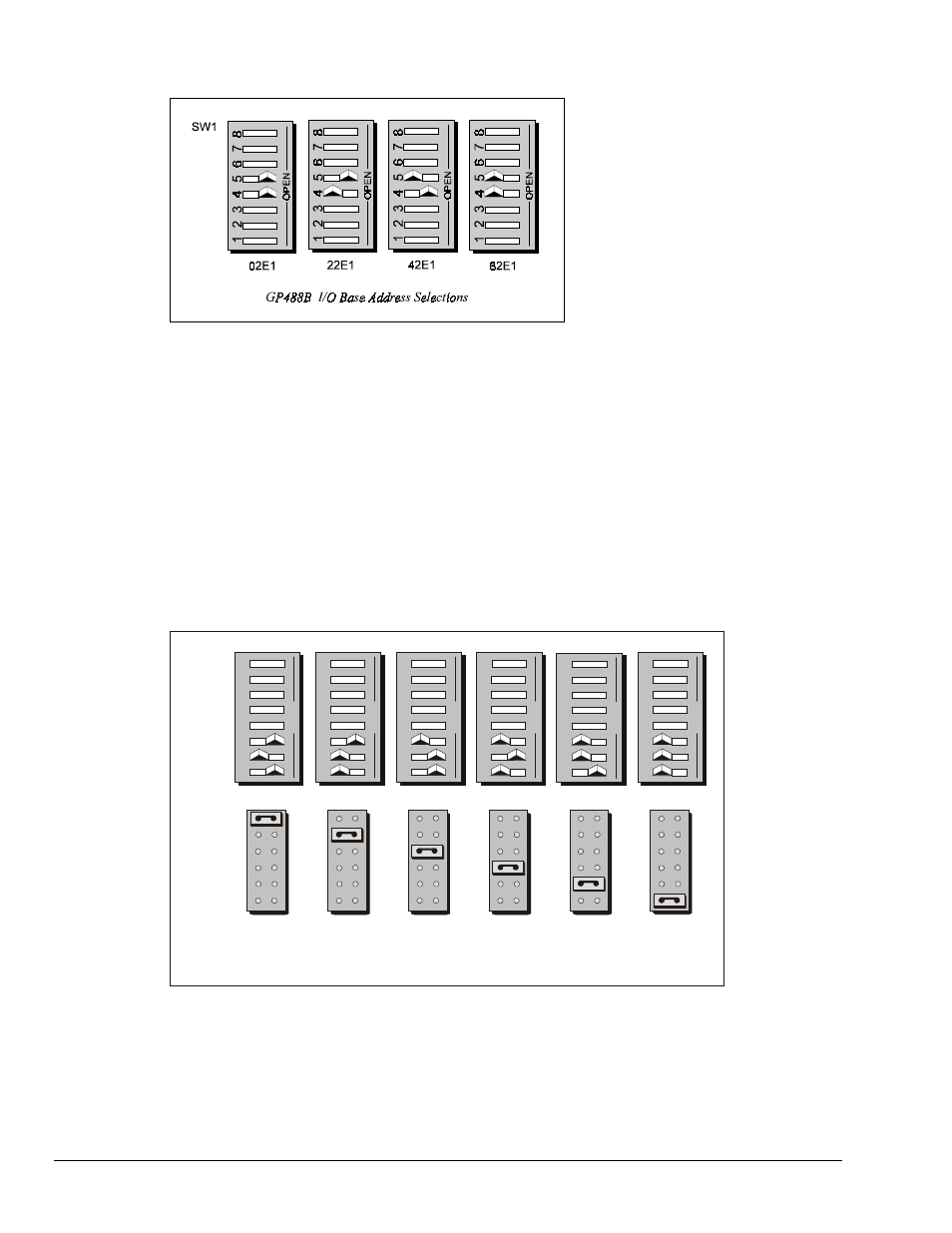
Configuring the GP488B/MM PC104 Interface I/O Base Address
The factory default I/O base address is
02E1
. If this creates a conflict, reset SW1 microswitches 4 and 5
according to the figure and following table. The register addresses will be automatically relocated at fixed
offsets from the base address. If reset, record the new Input/Output (I/O) address being used.
The I/O base address sets the addresses used by the computer to communicate with the IEEE 488 interface
hardware on the board. The address is normally specified in hexadecimal and can be
02E1
,
22E1
,
42E1
, or
62E1
. The registers of the IOT7210 IEEE 488 controller chip and other auxiliary registers are then located
at fixed offsets from the base address.
Most versions of Driver488 are capable of managing as many as four IEEE 488 interfaces. To do so, the
interface configurations must be arranged to avoid conflict. No two boards may have the same I/O address;
but they may, and usually should, have the same DMA channel and interrupt level.
Configuring the GP488B/MM PC104 Interface Interrupt (IRQ)
JP 3
IR Q 7
IR Q 5
IR Q 6
IR Q 4
IR Q 2
IR Q 3
S W 1
In te rru pt
L ev e l 6
In te rru p t
L e ve l 5
In te rru pt
L ev e l 2
In te rru pt
L ev e l 3
In te rru pt
L ev e l 4
G P 4 8 8 B /M M P C 1 0 4 In te rr u p t S e le c tio n s
6
7
8
6
7
8
6
7
8
6
7
8
6
7
8
5
5
5
5
5
2
3
2
3
2
3
2
3
2
3
OP
E
N
OP
E
N
OP
E
N
OP
E
N
OP
E
N
1
1
1
1
1
4
4
4
4
4
In te rru p t
L e ve l 7
6
7
8
5
2
3
OP
E
N
14
The factory default Interrupt (IRQ) is 5. If this creates a conflict, reset SW1 microswitches 1, 2, and 3, and
jumper JP3 according to the figure. The switch and jumper settings must both indicate the same interrupt
level for correct operation with interrupts. If reset, record the new Interrupt (IRQ) being used.