Alarms, Digital i/o channels, Web-temp block diagram – Measurement Computing WEB-TEMP User Manual
Page 8
WEB-TEMP User's Guide
Introducing the WEB-TEMP
8
The WEB-TEMP provides four integrated cold junction compensation (CJC) sensors for thermocouple
measurements, and built-in current excitation sources for resistive sensor measurements. Each CJC sensor is
dedicated to one of the four channel pairs. An open thermocouple detection feature lets you detect a broken
thermocouple. An on-board microprocessor automatically linearizes the measurement data according to the
sensor category.
Alarms
The WEB-TEMP features eight independent temperature alarms. Each alarm controls an associated digital I/O
channel as an alarm output. The input to each alarm is one of the temperature input channels. The output of each
alarm is software configurable as active high or low. The user-configurable threshold conditions activate each
alarm. When an alarm is activated, the associated DIO channel is driven to the active output state selected.
Digital I/O channels
Eight digital I/O channels are provided to communicate with external devices and to generate alarms. The
digital bits are software programmable for input or output. The digital output voltage is switch-selectable for
3.3 V or 5 V logic. A screw terminal is provided for pull-up or pull-down configuration.
The digital I/O channels power up in input mode unless the bit is configured for an alarm. When a digital bit is
configured as an alarm, that bit is configured as an output and assumes the state defined by the alarm
configuration.
If you need to log data or display data graphically
The WEB-TEMP displays current data read from the device, and does not log or store historical data. For
logging or trending needs, use the TracerDAQ software included on the Measurement Computing Data
Acquisition Software CD.
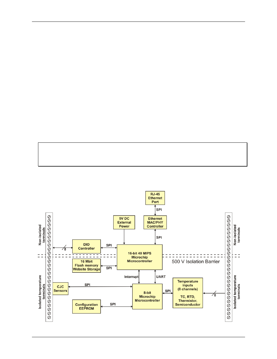
WEB-TEMP block diagram
WEB-TEMP functions are illustrated in the block diagram shown here.
Figure 1. Functional block diagram