Signal connections, Screw terminal pinout, Sensor inputs – Measurement Computing WEB-TEMP User Manual
Page 15
15
Chapter 3
Signal Connections
Screw terminal pinout
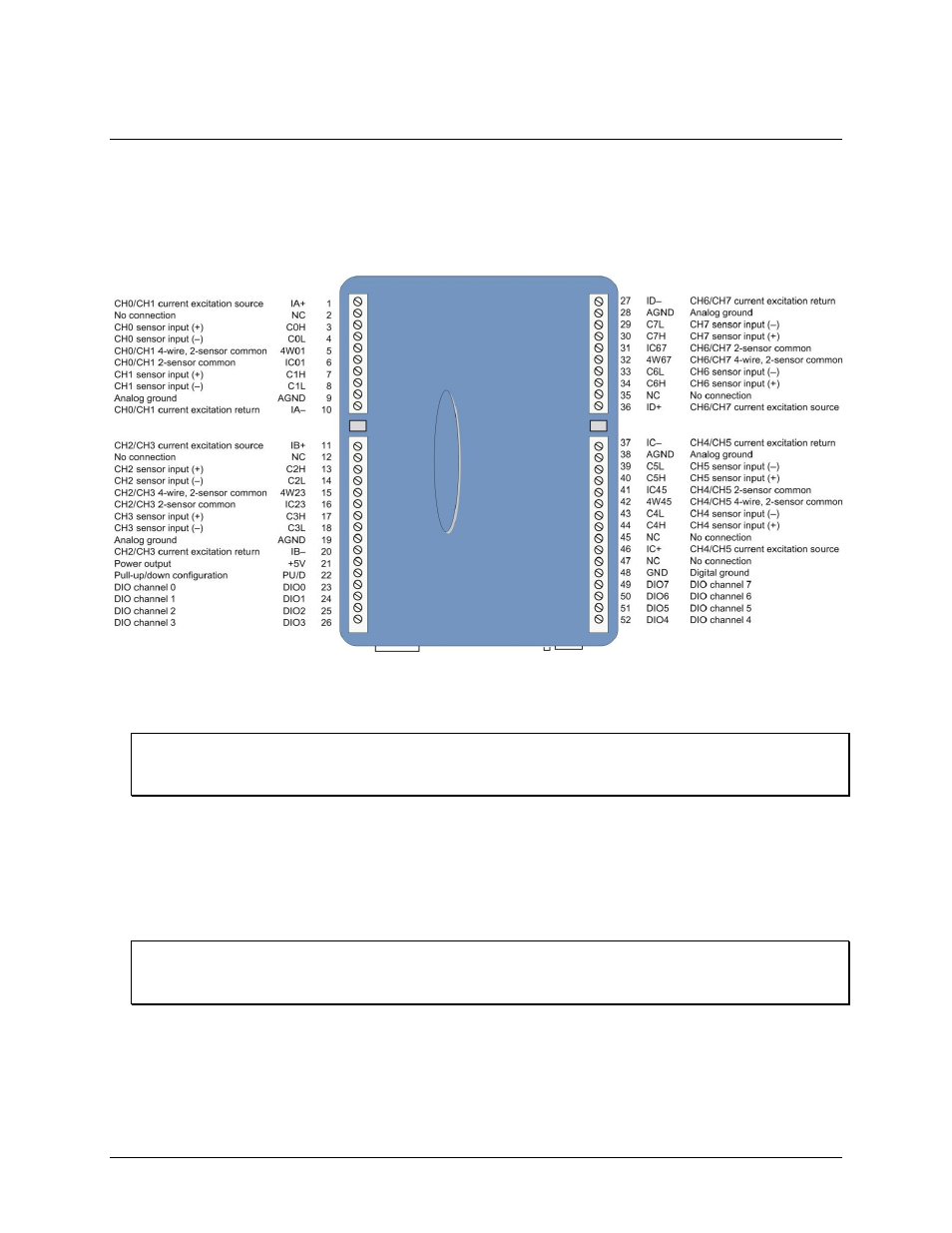
The WEB-TEMP has four rows of screw terminals. There are 26 connections on each side. Signals are
identified in Figure 2.
Figure 2. Screw terminal pinout
Do not make connections to the terminals labeled
NC
. Use 16 AWG to 30 AWG wire for your signal
connections.
Tighten screw terminal connections
When making connections to the screw terminals, be sure to tighten the screw until tight. Simply touching the
top of the screw terminal is not sufficient to make a proper connection.
Sensor inputs
The WEB-TEMP supports the following temperature sensor types:
Thermocouple – types J, K, R, S, T, N, E, and B
Resistance temperature detectors (RTDs) – 2, 3, or 4-wire measurement modes of 100 Ω platinum RTDs.
Thermistors – 2, 3, or 4-wire measurement modes.
Semiconductor temperature sensors – LM35, TMP35 or equivalent
Sensor selection
The type of sensor you select will depend on your application needs. Review the temperature ranges and
accuracies of each sensor type to determine which is best suited for your application.
You can connect up to eight temperature sensors to the differential sensor inputs (
C0H
/
C0L
to
C7H
/
C7L
).
Supported sensor categories include thermocouples, RTDs, thermistors, or semiconductor sensors.
Do not mix sensor categories within channel pairs. You can, however, mix thermocouple types (J, K, R, S, T, N,
E, and B) within channel pairs.