Data linearization, External components, Screw terminals – Measurement Computing WEB-TEMP User Manual
Page 23: Ethernet port, External power connector
WEB-TEMP User's Guide
Functional Details
23
Data linearization
An on-board microcontroller automatically performs linearization on RTD and thermistor measurements.
RTD measurements are linearized using a Callendar-Van Dusen coefficients algorithm (you select DIN,
SAMA, or ITS-90).
Thermistor measurements are linearized using a Steinhart-Hart linearization algorithm (coefficients
provided by the sensor manufacturer's data sheet).
External components
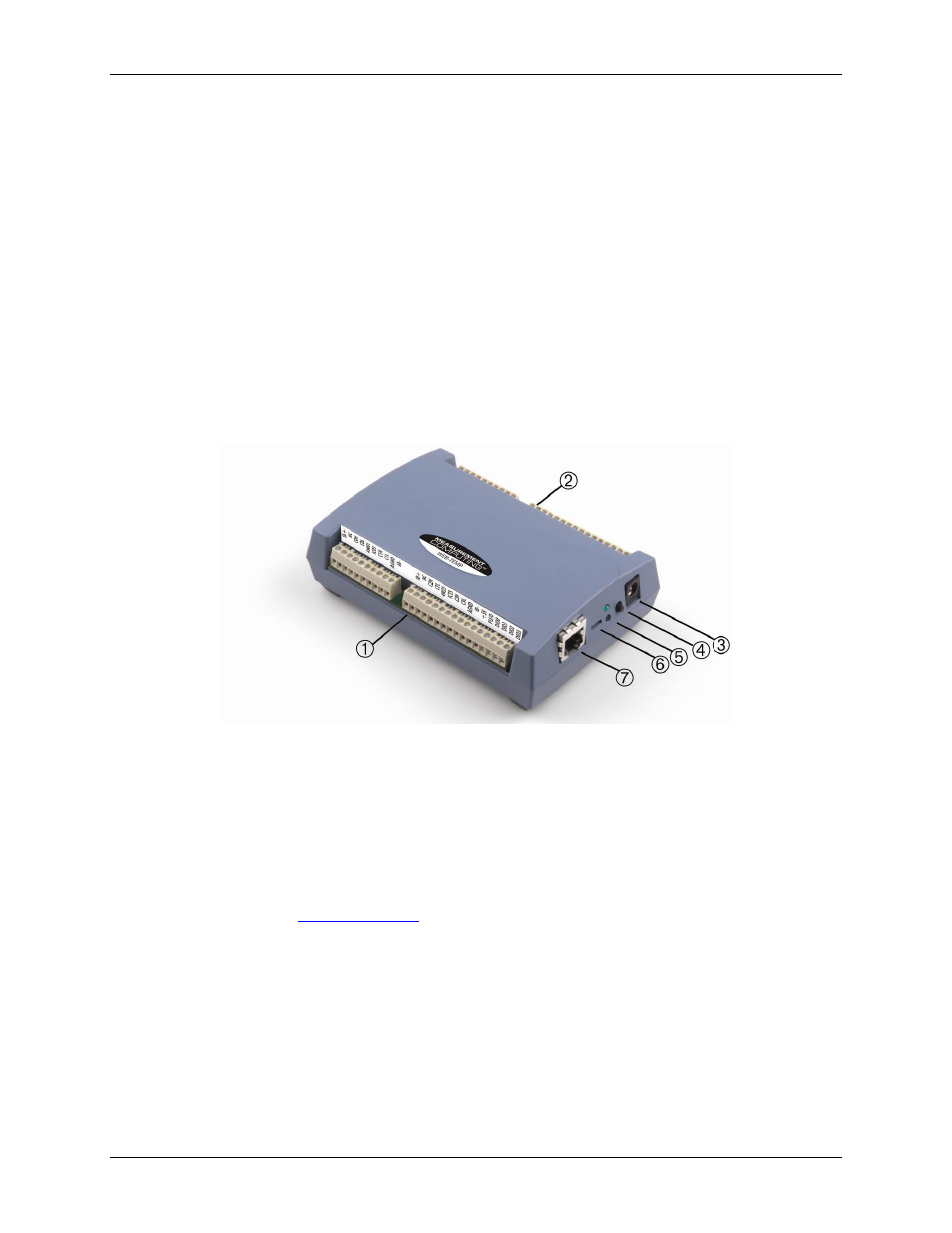
The WEB-TEMP has the following external components, as shown in Figure 11.
Screw terminals
Ethernet port
External power connector
Status LEDs (POWER/COMM and LINK/ACTIVITY)
Digital output voltage switch
Factory default reset button
1
Screw terminal pins 1 to 26
5
LEDs: POWER/COMM (top) and
LINK/ACTIVITY (bottom)
2
Screw terminal pins 27 to 52
6
Digital output voltage switch
3
Power connector
7
Ethernet port
4
Factory default reset button
Figure 11. WEB-TEMP component locations
Screw terminals
The screw terminals provide connections for sensors, digital channels, power, and ground. Detailed information
is provided in Chapter 3,
, beginning on page 15.
Ethernet port
The WEB-TEMP has one 10BASE-T communication port. The port connector is an eight-position RJ-45
connector. Use the Ethernet cable provided to connect the device to a local or wide area network or to a hub
attached to a single computer. Use a CAT-5 (or higher) shielded or unshielded twisted pair crossover cable to
connect directly to a computer. The maximum communication distance without using a repeater is 100 meters.
Data can transmit up to 100 meters at speeds of up to 100 Mbps using only one crossover Ethernet cable
connected to your computer.
External power connector
Use the supplied external power supply (MCC p/n PS-5V2AEPS) to power the WEB-TEMP.