Digital input/output, Temperature alarms, Memory – Measurement Computing WEB-TEMP User Manual
Page 34
WEB-TEMP User's Guide
Specifications
34
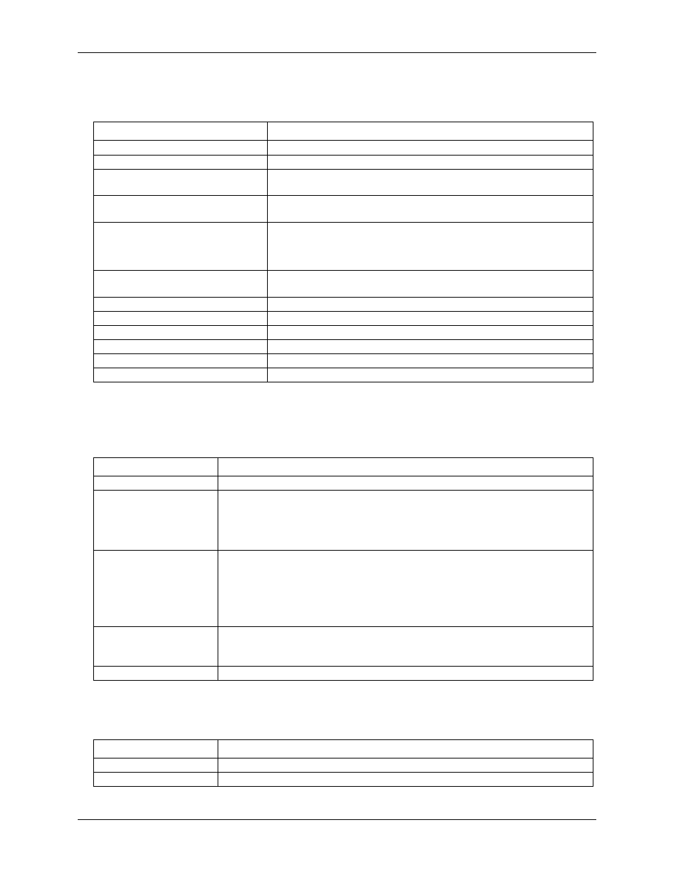
Digital input/output
Table 10. Digital input/output specifications
Parameter
Specification
Digital type
CMOS
Number of I/O
8 (DIO0 through DIO7)
Configuration
Independently configured for input or output.
Switch selectable output voltages: +5 V and +3.3 V
Power on conditions
Power on reset is Input mode except when bits are configured to operate as
alarms.
Pull-up/pull-down configuration
All pins are connected to 47 kΩ resistors that share a common point accessible
at Pin 22 of the device (PU/D). This pin is floating by default and is user-
configurable via external connection. For pull-up mode, connect this pin to pin
21 (+5V). For pull-down mode, connect this pin to Pin 48 (GND).
Digital I/O transfer rate (software paced)
Digital input: 50 port reads or single bit reads per second, typ.
Digital output: 100 port writes or single bit writes per second, typ.
Input high voltage (+5 V mode)
4 V min, 5.5 V absolute max
Input high voltage (+3.3 V mode)
2.64 V min, 5.5 V absolute max
Input low voltage (+5 V mode)
1 V max, –0.3 V absolute min
Input low voltage (+3.3 V mode)
0.66 V max, –0.3 V absolute min
Output low voltage (IOL = 2.5 mA)
0.6 V max
Output high voltage (IOH = –2.5 mA)
4.3 V min (+5 V mode), 2.7 V (+3.3 V mode)
Note 15:
Ground pins on the device labeled GND are isolated from AGND pins and from earth ground.
Temperature alarms
Table 11. Temperature alarm specifications
Parameter
Specification
Number of alarms
8 (one per digital I/O line)
Alarm functionality
Each alarm controls its associated digital I/O line as an alarm output. The input to each
alarm may be any of the analog temperature input channels. When an alarm is enabled, its
associated I/O line is set to output and driven to the appropriate state determined by the
alarm options and input temperature. The alarm configurations are stored in non-volatile
memory and are loaded at power on.
Alarm input modes
Alarm when input temperature > T1
Alarm when input temperature > T1, reset alarm when input temperature goes below T2
Alarm when input temperature < T1
Alarm when input temperature < T1, reset alarm when input temperature goes above T2
Alarm when input temperature is < T1 or > T2
T1 and T2 may be independently set for each alarm.
Alarm output modes
Disabled, digital I/O line may be used for normal operation
Enabled, active high output. The DIO line goes high when an alarm condition is met.
Enabled, active low output. The DIO line goes low when an alarm condition is met.
Alarm update rate
1 second
Memory
Table 12. Memory specifications
Parameter
Specification
EEPROM
512 bytes for sensor configuration
FLASH
2 MB for device configuration and website storage