Thermocouple connections, Wiring configuration, Rtd and thermistor connections – Measurement Computing WEB-TEMP User Manual
Page 17
WEB-TEMP User's Guide
Signal Connections
17
Thermocouple connections
A thermocouple consists of two dissimilar metals that are joined together at one end. When the junction of the
metals is heated or cooled, a voltage is produced that correlates to temperature.
The WEB-TEMP makes fully differential thermocouple measurements without requiring ground-referencing
resistors. A 32-bit floating point value in either a voltage or temperature format is returned by software. Open
thermocouple detection (OTD) is available for each thermocouple input. OTD automatically detects an open or
broken thermocouple.
Use the web browser or InstaCal to select the thermocouple type (J, K, R, S, T, N, E, and B) and one or more
input channels to connect the thermocouple.
Wiring configuration
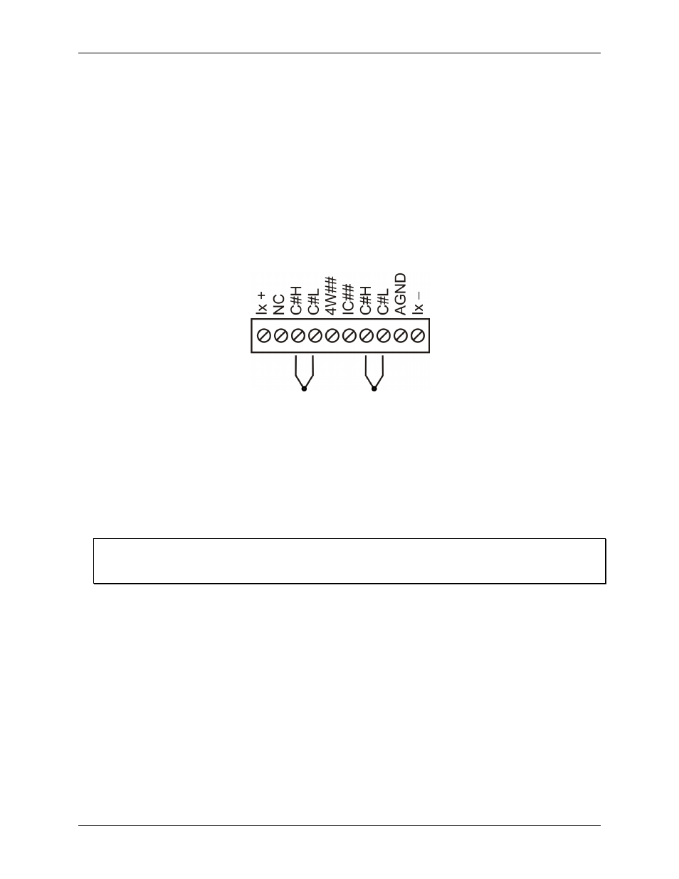
Connect the thermocouple to the WEB-TEMP using a differential configuration, as shown in Figure 3.
Figure 3. Typical thermocouple connection
Note
: There are two high/low channel pairs on each terminal. The # indicates the channel number. Do not make
connections to pin marked "NC".
Connect thermocouples to the WEB-TEMP such that they are floating with respect to AGND. The AGND pins
are isolated from earth ground, so connecting thermocouple sensors to voltages referenced to earth ground is
permissible as long as the isolation between the AGND pins and earth ground is maintained.
When thermocouples are attached to conductive surfaces, the voltage differential between multiple
thermocouples must remain within ±1.4 V. For best results, we recommend the use of insulated or ungrounded
thermocouples when possible.
Maximum input voltage between analog input and ground
The absolute maximum input voltage between an analog input and the isolated AGND pins is ±25 VDC when
the WEB-TEMP is powered on, and ±40 VDC when the WEB-TEMP is powered off.
If you need to increase the length of your thermocouple, use the same type of thermocouple wires to minimize
the error introduced by thermal EMFs.
RTD and thermistor connections
A resistance temperature detector (RTD) measures temperature by correlating the resistance of the RTD
element with temperature. A thermistor is a thermally-sensitive resistor that is similar to an RTD in that its
resistance changes with temperature — thermistors show a large change in resistance that is proportional to a
small change in temperature. The main difference between RTD and thermistor measurements is the method
used to linearize the sensor data.
RTDs and thermistors are resistive devices that require an excitation current to produce a voltage drop that can
be measured differentially across the sensor. The WEB-TEMP features four pairs of current excitation sources
(±IA to ±ID) for measuring resistive type sensors. Each current excitation terminal is dedicated to one pair of
sensor input channels:
IA+ is the current excitation source for channel 0 and channel 1
IB+ is the current excitation source for channel 2 and channel 3