Digital i/o connections, Configuring the dio channels to generate alarms – Measurement Computing WEB-TEMP User Manual
Page 21
WEB-TEMP User's Guide
Signal Connections
21
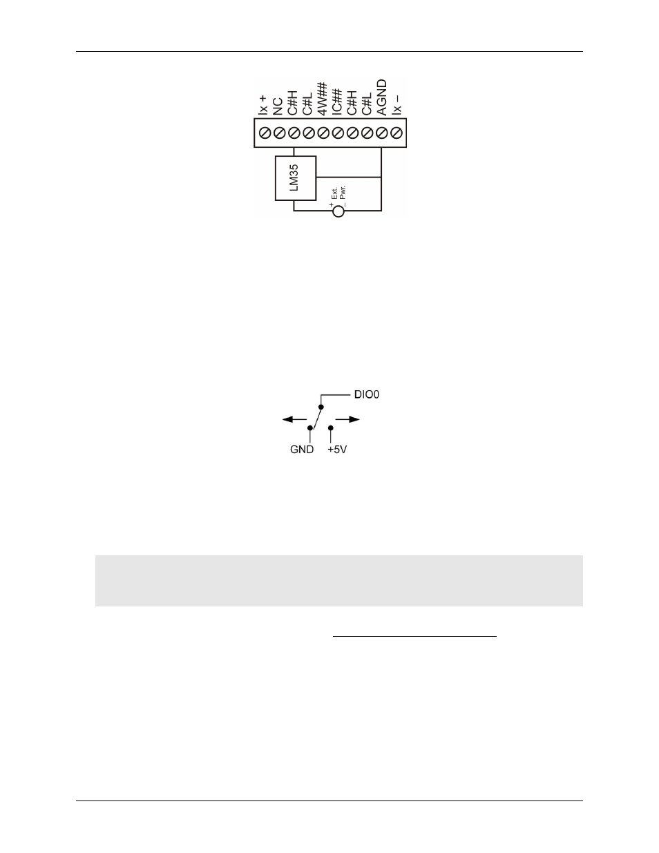
Figure 9. Semiconductor sensor measurement configuration
Digital I/O connections
Connect up to eight digital I/O lines to the screw terminals labeled
DIO0
to
DIO7
. Configure each digital bit for
either input or output. All digital I/O lines are connected through 47k to the
PU/D
pin, which is floating by
default. For a pull-up configuration, connect the
PU/D
terminal to the +5V terminal. For a pull-down
configuration, connect the
PU/D
terminal to the
GND
terminal.
When configuring the digital bits for input, the digital I/O terminals can detect the state of a TTL-compatible
device. The ground (
GND
) terminal (pin 48) provides a common ground for the digital I/O channels. Refer to
the schematic shown in Figure 10. If the switch is set to the +5V input, DIO0 reads TRUE (1). If the switch is
moved to GND, DIO0 reads FALSE (0).
Figure 10. Schematic showing switch detection by digital channel DIO0
When configuring the digital bits, use the switch on the side of the device to set the voltage to either 5 V or
3.3 V (see page 24 for more information). Refer to the digital I/O specification on page 34 for the maximum and
minimum threshold levels for each setting.
If a digital bit is set up as an alarm, that bit is configured for output and assumes the state defined by the alarm
configuration.
Caution! The ground pin labeled
GND
(pin 48) is isolated from the
AGND
pins and from earth ground. If a
connection is made to earth ground and
AGND
, the thermocouples are no longer isolated. In this
case, thermocouples must not be connected to any conductive surfaces that may be referenced to
earth ground.
For general information regarding digital signal connections and digital I/O techniques, refer to the Guide to
DAQ Signal Connections (available on our web site
Configuring the DIO channels to generate alarms
The WEB-TEMP features eight independent temperature alarms. All alarm options are configurable using the
web browser or InstaCal.
When a digital bit is configured as an alarm, that bit will be configured as an output and assume the state
defined by the alarm configuration.
Each alarm controls an associated digital I/O channel as an alarm output. The input to each alarm is one of the
temperature input channels. You set up the temperature conditions to activate an alarm, and the output state of
the channel (active high or low) when activated. When an alarm is enabled, its associated I/O line is set to
output and driven to the appropriate state determined by the alarm options and input temperature. Alarm
configuration settings are stored in non-volatile memory and are loaded on power up.